Density Functional Theory in Catalyst Design: A Comprehensive Guide from Fundamentals to AI-Driven Discovery
This article provides a comprehensive overview of the application of Density Functional Theory (DFT) in rational catalyst design, a paradigm shift from traditional trial-and-error approaches.
Density Functional Theory in Catalyst Design: A Comprehensive Guide from Fundamentals to AI-Driven Discovery
Abstract
This article provides a comprehensive overview of the application of Density Functional Theory (DFT) in rational catalyst design, a paradigm shift from traditional trial-and-error approaches. It covers foundational principles, including the Hohenberg-Kohn theorems and Kohn-Sham equations, and details methodological considerations for modeling both homogeneous and heterogeneous catalytic systems. The review further addresses key challenges such as functional selection, treatment of dispersion forces, and system size limitations, while exploring advanced topics like coverage effects and microkinetic modeling. Finally, it examines the growing integration of DFT with machine learning and generative AI for accelerated catalyst discovery and optimization, highlighting its implications for developing next-generation catalysts in energy and biomedical applications.
DFT Fundamentals: From Quantum Principles to Catalytic Insights
Density Functional Theory (DFT) has emerged as the most widely used computational method for electronic structure calculations in materials science and heterogeneous catalysis, representing a fundamental shift from wavefunction-based approaches to density-based formalism [1]. This transformation has proven particularly valuable in catalyst design research, where it provides an optimal compromise between accuracy and computational cost compared to semi-empirical methods or more accurate but computationally expensive wavefunction-theory-based approaches like coupled-cluster [1]. For researchers investigating catalytic mechanisms, DFT enables the determination of crucial properties including adsorption energies, equilibrium structures, transition state structures, and activation barriers for elementary reaction steps—parameters often difficult or impossible to obtain experimentally [2]. The theory's foundation rests upon two revolutionary mathematical theorems developed by Hohenberg and Kohn, and the practical implementation scheme introduced by Kohn and Sham, which together form the cornerstone of modern computational approaches to catalyst design and characterization.
Theoretical Foundations: The Hohenberg-Kohn Formalism
The Hohenberg-Kohn Theorems
The entire field of density functional theory is built upon two fundamental mathematical theorems proved by Hohenberg and Kohn [1]. The first Hohenberg-Kohn theorem establishes that "the ground-state electron density uniquely determines all properties, including energy and wavefunction, of the ground state" [1]. More formally, this theorem states that the external potential ( v{\text{ext}}(\mathbf{r}) ) is uniquely determined by the ground state electron density ( \rho(\mathbf{r}) ), and since ( v{\text{ext}}(\mathbf{r}) ) fixes the Hamiltonian, the entire system is uniquely determined by ( \rho(\mathbf{r}) ) [3]. This represents a significant conceptual simplification, as the electron density depends on only three spatial coordinates, compared to the 3N coordinates required to describe the many-electron wavefunction.
The second Hohenberg-Kohn theorem provides the variational principle for the density functional. It states that the ground-state energy can be obtained through the minimization of the energy functional ( E[\rho] ), and the density that minimizes this functional is the exact ground-state density [3]. This theorem can be expressed mathematically as:
where ( F[\rho] ) is a universal functional of the density that accounts for the kinetic energy and electron-electron interactions [3]. The minimization is performed under the constraint that the density integrates to the total number of electrons N [1].
Mathematical Formulation of the Theorems
Levy provided a particularly simple proof of the Hohenberg-Kohn theorem by defining a functional ( F[\rho] ) as:
[ F[\rho] = \min{\Psi \rightarrow \rho} \langle \Psi | \hat{T} + \hat{V}{ee} | \Psi \rangle ]
where the minimization is over all wavefunctions Ψ that yield the density ρ [3]. For a given external potential ( v_{\text{ext}}(\mathbf{r}) ), the total energy functional is:
[ E{v{\text{ext}}}[\rho] = F[\rho] + \int v_{\text{ext}}(\mathbf{r}) \rho(\mathbf{r}) d\mathbf{r} ]
The ground state energy is found by minimizing this expression over all N-electron densities ρ:
[ E0 = \min{\rho} E{v{\text{ext}}}[\rho] ]
This formal structure, while mathematically rigorous, does not immediately suggest practical computation methods, as the exact form of the universal functional F[ρ] remains unknown [3].
Table 1: Key Components of the Hohenberg-Kohn Formalism
| Component | Mathematical Expression | Physical Significance | ||
|---|---|---|---|---|
| Electron Density | ( \rho(\mathbf{r}) = \sum_i N | \varphi_i(\mathbf{r}) | ^2 ) [4] | Probability density of electrons at position r |
| Universal Functional | ( F[\rho] = T[\rho] + V_{ee}[\rho] ) | Contains kinetic and electron-electron interaction terms | ||
| Energy Functional | ( E[\rho] = F[\rho] + \int v_{\text{ext}}(\mathbf{r}) \rho(\mathbf{r}) d\mathbf{r} ) | Total energy as a functional of density | ||
| Variational Principle | ( E0 = \min{\rho} E{v{\text{ext}}}[\rho] ) | Foundation for finding ground state |
The Kohn-Sham Approach: From Theory to Practical Implementation
The Kohn-Sham Equations
While the Hohenberg-Kohn theorems established the theoretical foundation, the practical implementation of DFT became feasible through the approach introduced by Kohn and Sham in 1965 [4]. The key insight was to replace the original system of interacting electrons with a fictitious system of non-interacting particles that generate exactly the same electron density as the physical system of interacting particles [4]. This clever reformulation avoids the difficulty of directly dealing with the complex electron-electron interactions.
In the Kohn-Sham framework, the kinetic energy functional, which is challenging to express directly in terms of the density, is computed exactly for the non-interacting system using orbitals. The Kohn-Sham equations take the form of a Schrödinger-like equation for these non-interacting particles:
[ \left(-\frac{\hbar^2}{2m}\nabla^2 + v{\text{eff}}(\mathbf{r})\right)\varphii(\mathbf{r}) = \varepsiloni \varphii(\mathbf{r}) ]
where ( \varphii(\mathbf{r}) ) are the Kohn-Sham orbitals and ( \varepsiloni ) are the corresponding orbital energies [4]. The electron density is constructed from these orbitals:
[ \rho(\mathbf{r}) = \sumi^N |\varphii(\mathbf{r})|^2 ]
The effective potential ( v_{\text{eff}}(\mathbf{r}) ) is given by:
[ v{\text{eff}}(\mathbf{r}) = v{\text{ext}}(\mathbf{r}) + e^2 \int \frac{\rho(\mathbf{r}')}{|\mathbf{r} - \mathbf{r}'|} d\mathbf{r}' + \frac{\delta E_{\text{xc}}[\rho]}{\delta \rho(\mathbf{r})} ]
where the terms represent the external potential, the Hartree (Coulomb) potential, and the exchange-correlation potential, respectively [4].
The Kohn-Sham Self-Consistent Cycle
The solution of the Kohn-Sham equations follows an iterative self-consistent procedure, which can be visualized as follows:
Figure 1: The Kohn-Sham self-consistent cycle for solving the single-particle equations. The process iterates until convergence in the electron density or total energy is achieved, typically requiring 10-100 iterations depending on the system and initial guess.
Total Energy Expression in Kohn-Sham Theory
In the Kohn-Sham approach, the total energy of a system is expressed as a functional of the charge density:
[ E[\rho] = Ts[\rho] + \int d\mathbf{r} \, v{\text{ext}}(\mathbf{r}) \rho(\mathbf{r}) + E{\text{H}}[\rho] + E{\text{xc}}[\rho] ]
where:
- ( T_s[\rho] ) is the kinetic energy of the non-interacting Kohn-Sham system
- ( \int d\mathbf{r} \, v_{\text{ext}}(\mathbf{r}) \rho(\mathbf{r}) ) is the interaction with the external potential
- ( E{\text{H}}[\rho] ) is the Hartree (Coulomb) energy: [ E{\text{H}}[\rho] = \frac{e^2}{2} \int d\mathbf{r} \int d\mathbf{r}' \, \frac{\rho(\mathbf{r}) \rho(\mathbf{r}')}{|\mathbf{r} - \mathbf{r}'|} ]
- ( E_{\text{xc}}[\rho] ) is the exchange-correlation energy, which contains all the many-body effects [4]
The relationship between the total energy and the Kohn-Sham orbital energies is given by:
[ E = \sumi^N \varepsiloni - E{\text{H}}[\rho] + E{\text{xc}}[\rho] - \int \frac{\delta E_{\text{xc}}[\rho]}{\delta \rho(\mathbf{r})} \rho(\mathbf{r}) \, d\mathbf{r} ]
It is important to note that the Kohn-Sham orbital energies ( \varepsilon_i ) generally have limited direct physical meaning, except in the context of Koopmans' theorem [4].
Exchange-Correlation Functionals: Approximations and Limitations
The Local Density Approximation and Beyond
The only unknown term in the Kohn-Sham energy expression is the exchange-correlation functional ( E_{\text{xc}}[\rho] ), which must be approximated in practice. The most basic approximation is the Local Density Approximation (LDA), which assumes that the exchange-correlation energy at a point r can be approximated by that of a homogeneous electron gas with the same density:
[ E{\text{xc}}^{\text{LDA}}[\rho] = \int \rho(\mathbf{r}) \varepsilon{\text{xc}}(\rho(\mathbf{r})) d\mathbf{r} ]
where ( \varepsilon_{\text{xc}}(\rho) ) is the exchange-correlation energy per particle of a homogeneous electron gas of density ρ [3]. While LDA works surprisingly well for systems where the density varies slowly, it has significant limitations for strongly correlated systems and tends to overbind molecules and solids [3].
To address the limitations of LDA, more sophisticated functionals have been developed, including Generalized Gradient Approximations (GGA) that incorporate the gradient of the density:
[ E_{\text{xc}}^{\text{GGA}}[\rho] = \int f(\rho(\mathbf{r}), \nabla \rho(\mathbf{r})) d\mathbf{r} ]
Popular GGA functionals include the Perdew-Burke-Ernzerhof (PBE) functional, which is widely used in catalytic applications [2]. Further improvements include meta-GGA functionals that incorporate the kinetic energy density, and hybrid functionals that mix a portion of exact Hartree-Fock exchange with DFT exchange.
Table 2: Common Exchange-Correlation Functionals in Catalysis Research
| Functional Type | Examples | Advantages | Limitations |
|---|---|---|---|
| LDA | SVWN | Simple, relatively fast | Overbinding, poor for molecules |
| GGA | PBE, PW91 | Better for molecules, widely used | Underestimates barriers, band gaps |
| Meta-GGA | SCAN, TPSS | Improved for diverse bonding | Higher computational cost |
| Hybrid | B3LYP, HSE06 | Better band gaps, barriers | High computational cost |
| Van der Waals | vdW-DF, DFT-D | Accounts for dispersion | Parameterization dependencies |
Limitations of Current Approximations
Despite the remarkable success of DFT, important limitations persist in its practical applications. For strongly correlated systems where an independent particle picture breaks down, such as transition metal oxides (e.g., FeO, MnO, NiO), standard functionals like LDA and GGA are very inaccurate [3]. These functionals also struggle with describing van der Waals bonding and provide only a poor description of hydrogen bonding, which is essential for most biochemical applications [3].
In the context of catalysis, standard GGA functionals tend to underestimate reaction barriers, band gaps of materials, and the energies of dissociating molecular ions [2]. These limitations have prompted the development of various correction schemes, including the DFT+U approach for strongly correlated systems [2] and specialized van der Waals functionals for dispersion interactions [2].
Computational Protocols for Catalytic Applications
Model Selection for Heterogeneous Catalysis
The reliability of DFT calculations in catalysis research depends critically on the appropriate selection of computational models. For heterogeneous catalysis, the most common approach involves using slab models to represent catalyst surfaces [2]. These models should:
- Include appropriate crystal facets based on the morphology of the real catalytic nanoparticles
- Be sufficiently thick to properly describe surface properties (typically 3-5 atomic layers)
- Use adequate vacuum separation between periodic images (typically 10-15 Å)
- Employ appropriate k-point sampling for Brillouin zone integration
For supported metal catalysts, model development becomes more challenging. Recent approaches include single-atom catalysts (SACs) models, where metal atoms are anchored to support surfaces [1], and models that attempt to capture metal-support interactions [5].
Calculation of Catalytic Properties
The application of DFT in catalysis research typically focuses on calculating several key properties:
Adsorption energies are calculated as: [ E{\text{ads}} = E{\text{surface+adsorbate}} - E{\text{surface}} - E{\text{adsorbate}} ] where more negative values indicate stronger adsorption [1].
Reaction energy barriers are determined through transition state search methods such as the nudged elastic band (NEB) method or dimer method, followed by frequency calculations to confirm the transition state (exactly one imaginary frequency) [1].
Electronic structure descriptors like the d-band center have been proved as promising descriptors for rationalizing electrocatalytic activity [1]. The d-band center model provides an approximate description of bond formation at transition metal surfaces, showing that adsorption becomes stronger with the upshift of the d-band center toward the Fermi level [2].
Table 3: Key Computational Tools and Approaches for DFT in Catalysis Research
| Resource Category | Specific Examples | Application in Catalysis Research |
|---|---|---|
| DFT Software | VASP, Quantum ESPRESSO, Gaussian, CP2K | Electronic structure calculations with periodic or cluster models |
| Transition State Search | Nudged Elastic Band (NEB), Dimer Method | Location of transition states and reaction pathways |
| Basis Sets | Plane Waves, Atomic Orbitals, PAW Pseudopotentials | Representation of electronic wavefunctions |
| Analysis Tools | Bader Analysis, DOS, PDOS, Charge Analysis | Electronic structure analysis and descriptor extraction |
| Microkinetic Modeling | CATKIN, KMOS | Conversion of DFT energies to reaction rates |
Application to Catalyst Design: Case Studies and Protocols
Protocol: DFT Calculation of Adsorption Energies
Purpose: To determine the binding strength of molecules on catalyst surfaces, a crucial parameter in catalytic activity assessment.
Procedure:
- Geometry Optimization
- Build the clean surface model (slab) with appropriate Miller indices
- Fully optimize the slab structure until forces are below 0.01 eV/Å
- Place the adsorbate molecule at various plausible sites on the surface
- Optimize the adsorbate-surface system until convergence
Single-Point Energy Calculations
- Calculate the total energy of the optimized surface-adsorbate system
- Calculate the total energy of the clean surface with the same geometry
- Calculate the total energy of the isolated gas-phase molecule
Energy Analysis
- Compute adsorption energy using the formula above
- Perform Bader charge analysis to understand electronic redistribution
- Analyze electronic density of states to identify interaction mechanisms
Validation: Compare with experimental temperature-programmed desorption (TPD) data when available.
Case Study: Charge-Modulated Switchable CO2 Capture
DFT calculations have enabled the formulation of novel catalytic and capture strategies, such as the charge-modulated switchable CO2 capture using boron nitride (BN) nanosheets and nanotubes [1]. This approach, proposed based on DFT studies, demonstrates that:
- CO2 molecules weakly adsorb on neutral BN
- When excess electrons are injected, CO2 adsorption is dramatically enhanced
- As excess electrons are removed, adsorbed CO2 is easily released
- Charged BN nanomaterials show high selectivity in separating CO2 from gas mixtures like CO2/CH4 and CO2/H2 [1]
Subsequent DFT investigations explored conductive borophene nanosheets as a promising candidate for this application, overcoming the high band gap challenge of BN materials [1]. This case study illustrates how DFT calculations can guide the exploration of novel sorbent materials with higher selectivity, capacity, and ideal thermodynamics.
Protocol: Reaction Mechanism and Barrier Calculations
Purpose: To determine the complete reaction pathway and rate-determining steps for catalytic reactions.
Procedure:
- Reactant and Product State Identification
- Optimize geometry of initial reactant state (RS)
- Optimize geometry of final product state (PS)
- Confirm both are local minima through frequency calculations
Transition State Search
- Use NEB method to generate initial guess of reaction path
- Refine the transition state using climbing-image NEB or dimer method
- Verify transition state through frequency calculation (exactly one imaginary frequency)
Reaction Pathway Analysis
- Calculate reaction energy: ΔE = E(PS) - E(RS)
- Calculate activation barrier: Ea = E(TS) - E(RS)
- Perform electronic structure analysis along the reaction path
Microkinetic Modeling (Optional)
- Convert DFT energies to free energies using thermodynamic corrections
- Compute rate constants using transition state theory
- Solve kinetic equations to obtain turnover frequencies
The Hohenberg-Kohn theorems and Kohn-Sham approach together form the fundamental theoretical foundation underlying modern computational catalysis research. While the formal exactness of DFT is guaranteed by the Hohenberg-Kohn theorems, the practical success of the method relies heavily on the Kohn-Sham scheme and the quality of approximate exchange-correlation functionals.
Despite limitations in describing strongly correlated systems and dispersion interactions, DFT has become an indispensable tool in catalyst design, enabling researchers to understand catalytic mechanisms at atomic resolution and screen potential catalyst materials without labor-intensive synthetic procedures [5]. Current research focuses on developing more accurate functionals, improving methods for modeling complex catalytic environments, and integrating DFT with machine learning approaches for accelerated catalyst discovery.
As computational power continues to grow and theoretical methods advance, DFT calculations are expected to play an increasingly important role in the rational design of catalysts for sustainable energy applications, environmental protection, and chemical synthesis, bridging the gap between theoretical chemistry and practical catalyst development.
Density Functional Theory (DFT) is a computational quantum mechanical modelling method widely used in physics, chemistry, and materials science to investigate the electronic structure of many-body systems, particularly atoms, molecules, and condensed phases [6]. By using functionals (functions of functions) that depend on the spatially dependent electron density, DFT provides a versatile framework for determining the properties of many-electron systems while avoiding the computational intractability of direct solutions to the many-electron Schrödinger equation [6]. This approach has become particularly valuable in catalyst design research, where understanding electronic behavior at the quantum level enables rational design of catalytic materials.
The foundational principle of DFT is that all ground-state properties of a quantum system, including the energy, are uniquely determined by the electron density distribution n(r) [6]. This revolutionary concept reduces the problem of solving for a wavefunction dependent on 3N spatial coordinates (for N electrons) to one of finding a density dependent on only three coordinates, dramatically simplifying computational demands while maintaining quantum mechanical accuracy in principle.
Theoretical Foundations
The Electronic Structure Problem
In quantum chemistry, the electronic structure of a system with N electrons is described by a wavefunction Ψ(r1, …, rN) that satisfies the many-electron time-independent Schrödinger equation [6]:
ĤΨ = [T̂ + V̂ + Û]Ψ = EΨ
where T̂ represents the kinetic energy of the electrons, V̂ represents the external potential (typically electron-nucleus interactions), and Û represents the electron-electron interaction energy [6]. The complexity of solving this equation grows exponentially with the number of electrons, making direct solutions impossible for all but the smallest systems.
Traditional wavefunction-based methods, such as Hartree-Fock and post-Hartree-Fock approaches, attempt to approximate the many-electron wavefunction directly, but become computationally prohibitive for larger systems relevant to catalyst design [6].
The Hohenberg-Kohn Theorems
The theoretical foundation of DFT rests on two fundamental theorems proved by Hohenberg and Kohn [6]:
- Theorem I: The ground-state electron density n(r) uniquely determines the external potential V(r) (up to an additive constant), and thus all properties of the system.
- Theorem II: A universal functional for the energy E[n] in terms of the density n(r) exists, and the exact ground-state density minimizes this functional.
These theorems establish that the electron density alone is sufficient to determine all ground-state properties, without need for the full many-electron wavefunction [6]. For catalyst design, this means that relatively simple density-based calculations can, in principle, predict complex catalytic behaviors.
The Kohn-Sham Approach
Kohn and Sham introduced a practical computational scheme by mapping the interacting system of electrons onto a fictitious system of non-interacting electrons with the same density [6]. This approach leads to the Kohn-Sham equations:
(-½∇² + Veff(r))ψi(r) = εiψi(r)
where Veff(r) = Vext(r) + ∫(n(r')/|r-r'|)d³r' + V_xc(r)
The Kohn-Sham equations must be solved self-consistently because the effective potential Veff depends on the electron density, which in turn depends on the Kohn-Sham orbitals ψi [7]. This formulation decomposes the total energy into manageable components:
Etot^DFT = Tnon-int + Eestat + Exc + E_nn
where Tnon-int is the kinetic energy of the non-interacting system, Eestat includes electron-nucleus attraction and classical electron-electron repulsion, Exc is the exchange-correlation energy, and Enn is the nucleus-nucleus repulsion [8].
Exchange-Correlation Functionals
The Exchange-Correlation Energy
The exchange-correlation energy Exc contains all quantum mechanical effects not captured by the other terms, including exchange (due to the antisymmetry of the wavefunction) and correlation (due to electron-electron interactions beyond mean-field approximation) [8]. The exact form of Exc is unknown, and developing accurate approximations constitutes the central challenge in DFT development.
For catalytic applications, the treatment of exchange and correlation is particularly important for describing adsorption energies, reaction barriers, and electronic properties of transition metal complexes—all critical factors in catalyst performance.
Hierarchy of Functionals
Table 1: Classification of Exchange-Correlation Functionals
| Functional Type | Dependence | Examples | Computational Cost | Typical Applications in Catalysis |
|---|---|---|---|---|
| Local Density Approximation (LDA) | Local density n(r) | Slater+Perdew-Zunger [7] | Low | Baseline calculations, homogeneous systems |
| Generalized Gradient Approximation (GGA) | Density n(r) and its gradient ∇n(r) | PBE [7], PW91 [9] | Low-medium | Structural optimization, surface adsorption |
| Meta-GGA | Density, gradient, and kinetic energy density τ(r) | SCAN [7], MCML [8] | Medium | Reaction energies, simultaneous bulk/surface properties |
| Hybrid | Mix of HF exchange with semi-local functionals | B3LYP [9], HSE06 [7] | High | Molecular systems, band gaps, reaction barriers |
| Machine Learning | Learned from high-level data | DM21 [8], MCML [8] | Varies | Specialized properties, uncertainty quantification |
Local Density Approximation (LDA)
LDA is the simplest approximation, where the exchange-correlation energy at each point in space is that of a homogeneous electron gas with the same density [10]:
Exc^LDA[n] = ∫ n(r) εxc(n(r)) d³r
The exchange component has an exact analytical form: E_x^LDA[n] = -¾(3/π)^{1/3} ∫ n(r)^{4/3} d³r [10]. The correlation component is derived from quantum Monte Carlo simulations of the homogeneous electron gas [10]. While LDA provides a reasonable starting point, it tends to overbind, making bond lengths too short and binding energies too large—a significant limitation for accurate catalyst modeling.
Generalized Gradient Approximations (GGA)
GGA functionals incorporate the gradient of the electron density to account for inhomogeneities in real systems [7]:
Exc^GGA[n] = ∫ εxc(n(r), ∇n(r)) d³r
The PBE (Perdew-Burke-Ernzerhof) functional is widely used in solid-state physics and catalysis research for geometry optimization [7]. GGAs generally improve upon LDA for molecular properties and surface energies, making them suitable for preliminary catalyst screening.
Meta-GGA Functionals
Meta-GGAs include additional dependence on the kinetic energy density τ(r) = Σi^N (1/2)|∇ψi(r)|², enabling detection of local bonding character [8]:
Exc^MGGA[n] = ∫ εxc(n(r), ∇n(r), ∇²n(r), τ(r)) d³r
Functionals like SCAN and machine-learned functionals such as MCML can simultaneously describe diverse materials properties with good accuracy [8] [7]. For catalyst design, meta-GGAs offer improved performance for both reaction energies and lattice properties without the computational cost of hybrid functionals.
Hybrid Functionals
Hybrid functionals mix a fraction of exact Hartree-Fock exchange with semi-local DFT exchange [7]:
Exc^hybrid = α Ex^HF + (1-α) Ex^SL + Ec^SL
The HSE06 functional is particularly popular for periodic systems in catalysis research because it screens the long-range HF exchange, improving computational efficiency [7]. Hybrid functionals typically provide better band gaps and reaction barriers but at significantly higher computational cost.
Machine-Learned Functionals
Recent advances include machine-learning techniques to develop functionals trained on high-level theoretical data and experimental benchmarks [8]. For example, the MCML functional focuses on optimizing the semi-local exchange in a meta-GGA while keeping correlation in GGA form, showing improved performance for surface chemistry [8]. These approaches can also provide uncertainty quantification through Bayesian ensemble methods [8].
Specialized Corrections
van der Waals Corrections
Standard semi-local functionals poorly describe dispersion interactions (van der Waals forces), which are crucial for molecular adsorption on catalyst surfaces [6] [8]. Non-local van der Waals functionals like VV10 and optimized functionals like VCML-rVV10 incorporate these effects explicitly [8].
DFT+U
For strongly correlated systems (e.g., transition metal oxides with localized d- or f-states), the DFT+U approach adds an on-site Coulomb repulsion term to mitigate self-interaction errors [8] [7]. Machine learning approaches now enable site- and reaction coordinate-dependent U parameters for surface reactions [8].
Computational Protocols for Catalyst Design
Workflow for Catalytic Property Prediction
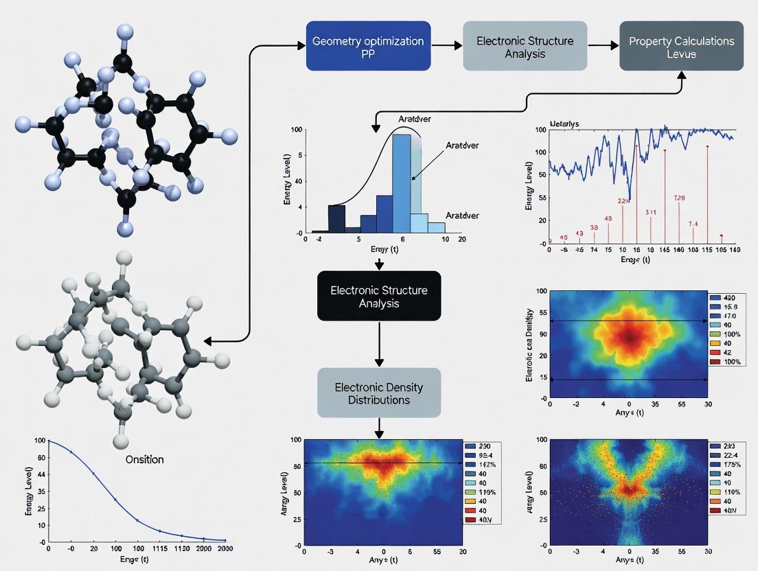
The following diagram illustrates a standardized computational workflow for evaluating catalytic properties using DFT:
Diagram 1: DFT workflow for catalytic property prediction.
Protocol: Surface Adsorption Energy Calculation
Objective: Determine the adsorption energy of a reaction intermediate on a catalytic surface.
Step-by-Step Methodology:
Surface Model Preparation:
- Select appropriate Miller indices for the catalytic surface (e.g., Pt(111) for FCC metals).
- Create a slab model with sufficient thickness (typically 3-5 atomic layers).
- Add vacuum layer (≥15 Å) to separate periodic images in the z-direction.
- Fix bottom 1-2 layers at bulk positions while relaxing top layers.
Bulk Optimization:
- Perform full geometry optimization of the bulk catalyst material.
- Use PBE functional with high k-point mesh (e.g., 15×15×15 for metals).
- Converge forces to <0.01 eV/Å and energy to <10⁻⁵ eV/atom.
- Record the optimized lattice parameters for surface model construction.
Clean Surface Optimization:
- Optimize the slab structure using the same functional.
- Use k-point mesh appropriate for surface calculations (e.g., 5×5×1).
- Converge forces on relaxed atoms to <0.02 eV/Å.
- Calculate the total energy E_slab.
Adsorbate Optimization:
- Optimize the gas-phase adsorbate molecule in a large box (e.g., 15×15×15 ų).
- Calculate the total energy Eadsorbategas.
Adsorption Complex Optimization:
- Place the adsorbate at appropriate surface sites (top, bridge, hollow).
- Optimize the full adsorption complex.
- Converge forces to <0.02 eV/Å.
- Calculate the total energy E_slab+adsorbate.
Adsorption Energy Calculation:
- Compute adsorption energy: Eads = Eslab+adsorbate - Eslab - Eadsorbate_gas
- Include zero-point energy corrections from vibrational frequency calculations if required.
Functional Selection Guide:
- For initial screening: PBE GGA functional
- For accurate adsorption energies: meta-GGA (SCAN) or hybrid (HSE06)
- For dispersion-dominated adsorption: PBE+vdW or VCML-rVV10
Protocol: Catalytic Reaction Barrier Calculation
Objective: Determine the activation energy for an elementary reaction step on a catalyst surface.
Methodology:
Initial and Final State Optimization:
- Optimize reactant and product states using the protocol in Section 4.2.
- Confirm local energy minima through vibrational frequency analysis (no imaginary frequencies).
Transition State Search:
- Nudged Elastic Band (NEB) Method: Place 5-8 images along the reaction path and optimize until the maximum force on the climbing image is <0.05 eV/Å.
- Dimer Method: Use for systems with known initial state but unknown reaction path.
- Verify transition state through single imaginary frequency corresponding to the reaction coordinate.
Energy Profile Construction:
- Calculate the electronic energy difference between transition state and initial state.
- Include zero-point energy corrections from vibrational analysis.
- For finite-temperature predictions, compute Gibbs free energy corrections.
Functional Considerations: Hybrid functionals (HSE06) are recommended for accurate barrier heights, though meta-GGAs provide reasonable compromise between cost and accuracy.
The Scientist's Toolkit
Research Reagent Solutions
Table 2: Essential Computational Tools for DFT in Catalyst Design
| Tool Category | Specific Examples | Function in Catalyst Research |
|---|---|---|
| DFT Software Packages | VASP [7], Quantum ESPRESSO, CASTEP [10] | Core computational engines for solving Kohn-Sham equations and computing electronic properties |
| Visualization & Analysis | VESTA, JMOL, VMD | Structure building, charge density visualization, and computational result analysis |
| Workflow Management | ASE (Atomic Simulation Environment), AiiDA | Automation of complex computational workflows and data management |
| Specialized Functionals | PBE [7], HSE06 [7], SCAN [7], MCML [8] | Exchange-correlation approximations tailored for specific catalytic properties |
| Benchmark Databases | CatApp, NOMAD, Materials Project | Reference data for validation and high-throughput screening of candidate materials |
Performance Assessment of Functionals
Table 3: Functional Performance for Catalytically Relevant Properties
| Functional | Binding Energies (MAE) | Reaction Barriers (MAE) | Lattice Constants (MAE) | Band Gaps (MAE) | Computational Cost Relative to LDA |
|---|---|---|---|---|---|
| LDA | 1.5-2.0 eV (overbinding) [10] | Typically underestimated [6] | 1-2% underestimate [10] | Severe underestimate [6] | 1.0× |
| PBE (GGA) | 0.2-0.3 eV [9] | 0.1-0.2 eV [9] | ~1% overestimate [7] | Underestimated [8] | 1.2× |
| SCAN (meta-GGA) | 0.1-0.15 eV [7] | 0.08-0.15 eV | <0.5% [7] | Improved but still low [8] | 1.5× |
| HSE06 (hybrid) | 0.1-0.2 eV | 0.05-0.1 eV | ~0.5% [7] | Good agreement [8] | 10-100× |
| MCML (machine-learned) | 0.05-0.1 eV [8] | Not reported | <0.5% [8] | Varies [8] | 1.5-2.0× |
Current Challenges and Future Directions
Despite its widespread success, DFT faces several challenges in catalyst design applications. The band gap problem—systematic underestimation of semiconductor and insulator band gaps—affects predictions of electronic properties in oxide catalysts and photocatalysts [6] [8]. Treatment of strongly correlated systems (e.g., transition metal oxides with localized d- or f-states) remains difficult without empirical corrections like DFT+U [8]. Accurate description of van der Waals interactions is crucial for molecular adsorption but requires specialized functionals [6] [8]. The quantitative prediction of reaction barriers is particularly sensitive to the exchange-correlation functional [6].
Future developments focus on machine-learned functionals that incorporate physical constraints while training on high-quality data [8], more sophisticated beyond-DFT methods for strongly correlated systems [8], and efficient implementations that make higher-level functionals accessible for routine catalytic screening [11]. For catalyst designers, these advances promise increasingly accurate predictions of catalytic activity, selectivity, and stability from first principles.
Density Functional Theory (DFT) stands as a cornerstone computational methodology in modern catalytic research, enabling scientists to probe the quantum mechanical foundations of catalytic processes at the atomic scale. This approach revolutionized computational materials science by reformulating the intractable many-electron Schrödinger equation into a tractable problem based on the electron density, a function of just three spatial coordinates [6]. For researchers in catalyst design, DFT provides a powerful virtual laboratory where catalytic systems can be investigated with unprecedented detail, from reaction energetics and electronic structure to surface dynamics and charge transfer processes.
The fundamental theorem underlying DFT states that all ground-state properties of a many-electron system, including energy and electronic structure, are uniquely determined by its electron density distribution ρ(r) [6] [12]. This conceptual breakthrough, pioneered by Hohenberg, Kohn, and Sham, forms the theoretical foundation upon which modern computational catalysis is built. The practical implementation of DFT occurs through the Kohn-Sham equations, which map the interacting system of electrons onto a fictitious system of non-interacting electrons moving within an effective potential [6] [11]. This effective potential incorporates the external potential from atomic nuclei, the classical Coulomb repulsion between electrons, and the quantum mechanical exchange-correlation effects that represent the most significant challenge in DFT approximations.
In contemporary catalyst design, DFT serves as an indispensable tool that bridges theoretical chemistry and materials engineering. By calculating critical parameters that are often difficult to measure experimentally, DFT provides fundamental insights into reaction mechanisms, active site characterization, and catalyst stability. The following sections detail the specific calculable properties in DFT, present structured protocols for their implementation, and demonstrate how these computations integrate into a comprehensive catalyst design workflow.
Calculable Properties in DFT for Catalysis
DFT enables the calculation of three fundamental categories of properties essential for understanding and predicting catalytic performance: energy landscapes, structural characteristics, and electronic properties. These computations provide the quantitative foundation for rational catalyst design.
Energy Calculations
Energy calculations form the predictive backbone of catalytic DFT studies, enabling the thermodynamic and kinetic assessment of reaction pathways.
Table 1: Energy Calculations in Catalytic DFT Studies
| Property | Catalytic Application | Key Outputs | Interpretation Guidelines |
|---|---|---|---|
| Adsorption Energies | Active site characterization, binding strength assessment | ΔEads (eV) | More negative values indicate stronger adsorption; Sabatier principle optimization |
| Reaction Energies | Thermodynamic feasibility of catalytic steps | ΔErxn (eV) | Exothermic (negative) vs. endothermic (positive) processes |
| Activation Barriers | Kinetic profiling, rate-determining step identification | Ea (eV) | Higher barriers indicate slower elementary steps; determines turnover frequency |
| Transition States | Reaction mechanism elucidation | Energy saddle point (eV), Imaginary frequency | Confirms connection between reactants and products along minimum energy path |
| Free Energy Landscapes | Potential-dependent electroanalysis (GC-DFT) | ΔG (eV) at applied potential | Determines thermodynamic overpotentials; identifies potential-dependent selectivity |
For electrochemical processes such as CO2 reduction, grand-canonical DFT (GC-DFT) extends standard energy calculations to incorporate electrode potential explicitly. This approach has revealed key descriptors such as CH* binding energy as the governing factor for acetate selectivity in CO electroreduction, enabling the AI-guided discovery of Cu/Pd and Cu/Ag catalysts with Faradaic efficiencies of 50% and 47%, respectively [13]. Similarly, DFT-based screening of single-atom catalysts (SACs) identified Pd@C5N as a superior CO2-to-CH4 catalyst with a limiting potential of just 0.42 V [14].
Structural Properties
Structural computations provide atomic-level insights into catalyst morphology, stability, and active site configuration.
Table 2: Structural Properties in Catalytic DFT Studies
| Property | Catalytic Application | Methodological Approach | Information Content |
|---|---|---|---|
| Equilibrium Geometry | Stable catalyst configuration | Ionic relaxation, lattice optimization | Ground-state atomic coordinates, lattice parameters |
| Surface Energies | Catalyst stability, morphology prediction | Slab model energy vs. bulk reference | Wulff shape construction; relative stability of crystal facets |
| Defect Formation Energies | Point defect, vacancy, dopant stability | Energy comparison with perfect lattice | Dominant defect types under synthesis conditions |
| Vibrational Frequencies | Spectroscopic fingerprinting (IR, Raman) | Phonon dispersion, molecular vibrations | Identification of adsorbed species, thermal properties |
| Charge Density Distribution | Bonding characterization, active site localization | 3D spatial visualization | Ionic/covalent/metallic bonding analysis; polarization effects |
Structural optimization through force minimization allows DFT to predict stable catalyst configurations, including surface reconstructions and defect structures that often govern catalytic activity. For example, DFT investigations of Y2CF2 monolayers confirmed their dynamic and thermodynamic stability while revealing semimetallic behavior and favorable metal atom diffusion barriers (6.8-28.6 eV), suggesting potential applications in battery technologies and electrocatalysis [15]. Elastic constant calculations further provide mechanical property assessment through energy changes induced by small atomic displacements, yielding Young's modulus, bulk modulus, and shear modulus critical for evaluating catalyst durability under operating conditions [12].
Electronic Properties
Electronic structure calculations reveal the fundamental origins of catalytic activity through quantum mechanical analysis of electron behavior.
Band Structure: DFT-calculated band structures provide critical insights into conductive behavior by mapping electron energy versus momentum relationships. The bandgap width directly determines whether a material exhibits metallic, semiconducting, or insulating characteristics, which governs charge transport in electrocatalysis [12] [16]. For instance, DFT revealed that indium-doped MoS2 possesses a dramatically reduced bandgap (0.02 eV) compared to pure MoS2 (2.09 eV), explaining its enhanced conductivity and catalytic performance [16]. Functional selection significantly impacts accuracy, with LDA and GGA typically underestimating bandgaps by ~40%, while hybrid functionals like HSE06 provide experimental agreement.
Density of States (DOS): The total and projected density of states offers a energy-resolved picture of electron availability. Integrated DOS near the Fermi level estimates effective carrier concentration, while projected DOS (PDOS) decomposes contributions from specific atomic orbitals (e.g., transition metal d-states or non-metal p-states) [16]. Orbital hybridization, indicated by overlapping PDOS peaks, reveals bonding characteristics critical to catalytic function, such as sp2 hybridization in graphene facilitating conjugated π-bonds that promote electron localization [16].
Work Function (WF): Surface-dependent WF calculations quantify electron confinement strength, with higher values indicating tighter electron binding. WF differences between crystal facets or materials drive interfacial polarization in heterostructures, a crucial energy dissipation mechanism in catalytic systems [16]. Strategic interfacial engineering leverages substantial WF disparities to enhance electron localization at heterojunctions, improving charge separation and catalytic activity.
Computational Protocols
Protocol for Surface Reaction Energy Calculations
This protocol details the methodology for computing adsorption energies and reaction energetics on catalyst surfaces, based on approaches used in CO2 electroreduction studies [13] [14].
Step 1: Surface Model Construction
- Select the appropriate crystal facet (e.g., Cu(211) for stepped surfaces, Pt(100) for terraces)
- Create a slab model with sufficient thickness (typically 3-5 atomic layers)
- Implement a vacuum layer of at least 15 Å to separate periodic images
- For surface reactions, use a p(2×2) or p(3×3) supercell to minimize adsorbate interactions
Step 2: DFT Calculation Parameters
- Employ the GGA-PBE functional for surface reactions (or HSE06 for bandgap-critical systems)
- Use a plane-wave basis set with kinetic energy cutoff of 400-500 eV
- Implement PAW pseudopotentials to describe core-electron interactions
- Set force convergence criterion to < 0.01 eV/Å for ionic relaxation
- Use a k-point mesh of (3×3×1) for surface Brillouin zone sampling
Step 3: Energy Computation
- Calculate the total energy of the clean relaxed surface (Esurface)
- Calculate the total energy of the isolated molecule in the gas phase (Emolecule)
- Calculate the total energy of the adsorbed system (Eadsorbate+surface)
- Compute adsorption energy: Eads = Eadsorbate+surface - Esurface - Emolecule
Step 4: Transition State Location
- Employ the Nudged Elastic Band (NEB) method with 5-7 intermediate images
- Use the Dimer method for refined saddle point optimization
- Verify the transition state by vibrational frequency analysis (exactly one imaginary frequency)
Protocol for Electronic Structure Analysis
This protocol describes the methodology for calculating and interpreting electronic properties relevant to catalysis [12] [16].
Step 1: Band Structure Calculation
- Perform initial geometry optimization with high accuracy criteria
- Identify high-symmetry points in the Brillouin zone (Γ, K, M, X, L)
- Run a self-consistent field (SCF) calculation with dense k-point mesh
- Calculate band structure along predetermined high-symmetry paths
- Analyze direct vs. indirect bandgaps and band degeneracies
Step 2: Density of States Analysis
- Compute total DOS with enhanced k-point sampling (>1000 points in full Brillouin zone)
- Perform projected DOS (PDOS) onto atomic orbitals of interest
- Decompose contributions by angular momentum (s, p, d, f orbitals)
- Integrate DOS near Fermi level (-2 eV to +2 eV) to estimate carrier concentration
- Identify orbital hybridization through PDOS peak alignment
Step 3: Work Function Calculation
- Model the appropriate surface slab with sufficient vacuum
- Compute electrostatic potential throughout the simulation cell
- Determine the vacuum potential level far from the surface
- Calculate WF as difference between vacuum level and Fermi energy
- Repeat for different crystal facets to assess anisotropy
The Catalyst Design Workflow
The integration of DFT calculations into catalyst design follows a systematic workflow that connects computational predictions with experimental validation. This pipeline has proven particularly effective in electrocatalysis, where DFT-derived descriptors guide the discovery of advanced materials.
This workflow exemplifies the modern paradigm of computational catalyst design. For CO electroreduction to acetate, researchers identified CH* binding energy as the key descriptor through DFT-based microkinetic modeling [13]. Active learning optimization predicted Cu/Pd (2:1) and Cu/Ag (3:1) alloys as promising candidates, which were subsequently synthesized and tested, achieving Faradaic efficiencies of 50% and 47% respectively—more than double that of pure Cu (21%) [13]. Similarly, for CO2-to-CH4 conversion, a five-step DFT screening strategy identified nine single-atom catalysts superior to conventional Cu(211), with Pd@C5N exhibiting a remarkably low limiting potential of 0.42 V [14].
The Scientist's Toolkit
Successful implementation of DFT calculations requires both software tools and computational approaches tailored to catalytic applications.
Table 3: Essential Computational Tools for Catalytic DFT
| Tool Category | Specific Examples | Catalytic Application | Function |
|---|---|---|---|
| DFT Software Packages | VASP, Quantum ESPRESSO, CASTEP, GPAW | General catalyst screening | Electronic structure calculation with periodic boundary conditions |
| Electronic Structure Analysis | VESTA, VASPKIT, BAND | DOS, band structure, charge density analysis | Visualization and processing of DFT outputs |
| Transition State Location | CI-NEB, Dimer Method, ART | Reaction pathway mapping | Location of saddle points and minimum energy paths |
| Microkinetic Modeling | CATKINAS, KMOS, ZACROS | Reaction rate prediction | Connecting electronic structure to catalytic rates |
| Machine Learning Integration | AMP, SchNet, PhysNet | Accelerated catalyst screening | Learning structure-property relationships from DFT data |
The integration of artificial intelligence with DFT represents a transformative advancement in computational catalysis. AI algorithms can predict electronic responses under physical constraints, accelerate parameter screening, and enhance DFT interpretation reliability [16]. For instance, large language models have been combined with grand-canonical DFT to accelerate the discovery of efficient electrocatalysts, successfully guiding the synthesis of asymmetric FeN4 sites for oxygen reduction reaction with superior stability (>90% activity retention after 30,000 cycles) [17]. Similarly, machine learning models (XGBoost, Random Forest) trained on DFT-derived features have identified key catalyst parameters—d-electron count, first ionization energy, d-band center, and atomic radius—as dominant factors governing CO2 reduction performance [14].
DFT calculations provide an indispensable toolkit for mapping the catalytic landscape through precise computation of energies, structures, and electronic properties. The protocols and methodologies outlined herein enable researchers to quantitatively connect atomic-scale phenomena with macroscopic catalytic performance. As DFT continues to evolve through integration with machine learning approaches and advanced computational frameworks, its predictive power in catalyst design will further accelerate the discovery of next-generation materials for sustainable energy and chemical processes. The successful application of these computational strategies, demonstrated through the guided discovery of high-performance catalysts for CO and CO2 electroreduction, underscores the transformative potential of DFT-driven catalyst design in addressing pressing challenges in renewable energy and sustainable chemistry.
In the realm of density functional theory (DFT) calculations for catalyst design, the selection of an appropriate basis set is not merely a technical detail but a fundamental strategic decision that directly determines the accuracy, reliability, and computational feasibility of simulations. Basis sets—the mathematical functions used to represent electronic orbitals—form the very foundation upon which quantum chemical calculations are built. For researchers investigating catalytic processes, whether in homogeneous, heterogeneous, or enzymatic systems, the choice between two predominant paradigms—plane-wave (PW) and atomic-centered (localized orbital) basis sets—carries significant implications for predicting adsorption energies, reaction barriers, and electronic properties with the precision required for rational catalyst design.
The critical importance of this selection stems from its direct connection to two pivotal aspects of computational modeling: (1) the faithfulness of physical representation of the electronic structure in diverse chemical environments, and (2) the practical computational cost associated with modeling realistic catalyst systems. A poorly chosen basis set can introduce artifacts such as basis set superposition error (BSSE) or fail to adequately describe key electronic effects, leading to qualitatively incorrect predictions regarding catalytic activity or selectivity [18] [19]. Conversely, an optimally chosen basis set provides the optimal compromise between accuracy and computational efficiency, enabling high-throughput screening of catalyst candidates or detailed mechanistic studies with predictive reliability.
This application note provides a comprehensive framework for selecting between plane-wave and atomic-centered basis sets within the specific context of DFT calculations for catalyst design. By synthesizing current theoretical understanding with practical benchmarking studies, we establish structured protocols to guide researchers in making informed methodological choices tailored to their specific catalytic systems and research objectives.
Theoretical Foundations: Plane-Wave vs. Atomic-Centered Basis Sets
Fundamental Definitions and Mathematical Representations
Plane-wave (PW) basis sets expand the electronic wavefunctions as a superposition of periodic functions defined throughout the simulation cell:
[ \psii(\mathbf{r}) = \sum{\mathbf{G}} c_{\mathbf{G}} e^{i\mathbf{G} \cdot \mathbf{r}} ]
where (\mathbf{G}) represents the reciprocal lattice vectors, and the summation is truncated at a specific kinetic energy cutoff ((E_{\text{cut}} = \frac{\hbar^2 |\mathbf{G}|^2}{2m})) that determines the basis set quality [20] [19]. This uniform, spatially delocalized representation naturally embodies translational symmetry, making PWs the default choice for periodic systems.
Atomic-centered basis sets, also known as localized orbital basis sets, employ functions centered on atomic nuclei, typically as a linear combination of Gaussian-type orbitals (GTOs):
[ \phi\mu(\mathbf{r}) = \sump d{p\mu} Np r^{l} e^{-\alphap r^2} Y{lm}(\theta,\phi) ]
where (Y{lm}) are spherical harmonics, and the contraction coefficients (d{p\mu}) and exponents (\alpha_p) are optimized for specific elements [18] [21]. This atom-centered approach provides a chemically intuitive representation that naturally concentrates computational resources near atomic cores where electron density varies most rapidly.
Comparative Analysis of Fundamental Properties
Table 1: Fundamental Characteristics of Plane-Wave and Atomic-Centered Basis Sets
| Property | Plane-Wave Basis Sets | Atomic-Centered Basis Sets |
|---|---|---|
| Spatial Representation | Delocalized, uniform in real space | Localized on atomic centers |
| Systematic Improvability | Single parameter (cutoff energy) | Multiple parameters (cardinal number, diffuse functions) |
| Basis Set Superposition Error (BSSE) | Virtually nonexistent [19] | Can be significant, requires counterpoise correction [18] [19] |
| Computational Scaling | Favorable for dense k-point sampling | More favorable for hybrid functionals [20] |
| Default Applicability | Periodic systems (bulk crystals, surfaces) | Molecular systems, clusters [1] [18] |
| Core Electron Treatment | Typically uses pseudopotentials | Can treat all-electron or use effective core potentials |
Basis Set Selection Protocol for Catalytic Systems
The selection between plane-wave and atomic-centered basis sets hinges primarily on the dimensionality and electronic structure of the catalytic system under investigation. The following decision protocol provides a systematic approach for researchers.
Diagram 1: Decision workflow for basis set selection in catalytic systems. BSSE refers to basis set superposition error.
Application-Specific Selection Guidelines
Heterogeneous Catalysis (Periodic Systems)
For metallic surfaces and solid catalysts, plane-wave basis sets typically offer significant advantages. Benchmarking studies on Fe(110) surfaces demonstrate that PW basis sets achieve faster convergence for small slab models while maintaining superior stability for larger supercells [20]. The absence of BSSE is particularly advantageous when studying molecular adsorption on catalytic surfaces, where weak interactions (e.g., physisorption) must be accurately characterized [19].
Protocol for Metallic Surface Calculations:
- Initial Setup: Construct slab model with appropriate vacuum spacing (≥15 Å)
- Plane-Wave Cutoff: Converge total energy with respect to cutoff energy (typically 400-600 eV for transition metals)
- k-point Sampling: Implement Monkhorst-Pack grid with density sufficient to converge adsorption energies (<0.01 eV)
- Validation: Compare surface energies with localized basis set (e.g., pob-TZVP) when feasible
Homogeneous and Molecular Catalysis
For discrete molecular systems, organometallic complexes, and enzyme active sites, atomic-centered basis sets provide superior computational efficiency and more natural representation of local electronic structure. The ability to employ hybrid functionals without prohibitive computational cost makes them particularly valuable for studying reaction mechanisms where accurate electronic exchange is critical [18].
Protocol for Molecular Catalyst Systems:
- Basis Set Selection: def2-TZVP or def2-SVPD for exploratory scans; def2-QZVPP for final single-point energies
- Dispersion Correction: Include D3(BJ) empirical dispersion corrections [18]
- BSSE Management: Apply counterpoise correction for weakly interacting complexes [19]
- Solvation Effects: Incorporate implicit solvation models (e.g., SMD, COSMO) for solution-phase catalysis
Hybrid and Multiscale Systems
Emerging catalyst architectures such as single-atom catalysts (SACs), metal-organic frameworks (MOFs), and supported molecular catalysts present unique challenges that may benefit from mixed approaches. The Universal Model for Atoms (UMA) architecture recently introduced by Meta's FAIR team represents a promising direction, employing a Mixture of Linear Experts (MoLE) approach to unify diverse chemical datasets across multiple domains [22].
Performance Benchmarking and Convergence Protocols
Quantitative Comparison for Representative Systems
Table 2: Performance Benchmarks for Plane-Wave vs. Atomic-Centered Basis Sets
| System Type | Property | Plane-Wave Results | Atomic-Centered Results | Experimental/Reference |
|---|---|---|---|---|
| Fe(110) Surface [20] | Work Function | 4.70 eV | 4.92 eV | ~4.8 eV |
| Fe(110) Surface [20] | Surface Energy | 2.12 J/m² | 2.35 J/m² | 2.0-2.5 J/m² |
| Molecular Crystal [23] | THz Spectrum (RMSD) | - | PBE/pob-TZVP: 0.81 cm⁻¹ (H-bond) | Experimental reference |
| S22 Noncovalent Dimers [19] | MP2 Interaction Energy (MAE) | CBS Reference | aug-cc-pV5Z: 0.05 kcal/mol | - |
| Biomolecules [22] | Energy Accuracy (WTMAD-2) | - | OMol25-trained NNPs: near-DFT | High-level DFT reference |
Practical Implementation Protocols
Plane-Wave Convergence Protocol for Surface Calculations
Software: VASP, Quantum ESPRESSO, CASTEP System: Transition metal surface (e.g., Pt(111), Fe(110))
Pseudopotential Selection:
- Use PAW (Projector Augmented Wave) pseudopotentials
- Verify consistent treatment of valence electrons across compared elements
Energy Cutoff Convergence:
- Perform single-point calculations with increasing ENCUT (300-700 eV)
- Select cutoff where total energy change < 1 meV/atom
- Typical values: 400-520 eV for 3d metals, 250-400 eV for main group elements
k-point Grid Convergence:
- Start with Γ-point only for structure relaxation
- Increase k-point density until adsorption energies converge to <0.01 eV
- Typical grids: 3×3×1 to 11×11×1 for surface calculations
Vacuum Thickness Verification:
- Ensure minimal interaction between periodic images (≥15 Å)
- Confirm dipole corrections implemented for asymmetric slabs
Atomic-Centered Basis Set Protocol for Molecular Catalysts
Software: Gaussian, ORCA, CP2K/Quickstep System: Organometallic catalyst (e.g., transition metal complex)
Basis Set Hierarchy:
- Geometry optimization: def2-SVPD or def2-TZVP
- Single-point energy: def2-QZVPP
- Spectral properties: aug-cc-pVTZ (main group), def2-TZVP (metals)
BSSE Management:
- Apply counterpoise correction for intermolecular interactions
- Use Boys-Bernardi counterpoise correction for supramolecular systems
Integration Grid Selection:
- Use "UltraFine" grid in Gaussian or equivalent in other packages
- Verify integration accuracy for metal centers with large grids (99,590 points) [22]
The Computational Catalyst Design Toolkit
Table 3: Essential Research Reagent Solutions for Basis Set Implementation
| Tool/Resource | Type | Function | Application Context |
|---|---|---|---|
| VASP [20] | Software Package | Plane-wave DFT with PAW pseudopotentials | Periodic surfaces, solid catalysts, electrochemical interfaces |
| Gaussian [21] | Software Package | Molecular DFT with atomic-centered basis sets | Molecular catalysts, reaction mechanisms, spectroscopic properties |
| CRYSTAL [20] | Software Package | Periodic DFT with localized basis sets | Mixed-dimensionality systems, molecular crystals |
| def2 Basis Sets [18] | Atomic-Centered Basis Set | Balanced accuracy/efficiency for elements 1-86 | Molecular catalyst screening, mechanistic studies |
| cc-pVXZ Families [19] | Atomic-Centered Basis Set | Systematic correlation-consistent convergence | High-accuracy thermochemistry, noncovalent interactions |
| Pseudopotential Libraries | Pseudopotential Database | Consistent core electron treatment | Plane-wave calculations across periodic table |
| Basis Set Exchange [21] | Basis Set Repository | Access to standardized basis sets | Reproducible atomic-centered calculations |
| OMol25 Dataset [22] | Training Data | Neural network potential development | Large-scale catalyst screening with DFT accuracy |
Emerging Methods and Future Directions
The historical dichotomy between plane-wave and atomic-centered approaches is increasingly being bridged by methodological advances. The eSEN (equivariant Scalar-Efficient Network) architecture and UMA (Universal Models for Atoms) framework demonstrate how neural network potentials trained on massive computational datasets (e.g., OMol25 with 100+ million calculations) can achieve DFT-level accuracy while dramatically reducing computational cost [22]. These approaches effectively learn optimal representations that capture the strengths of both basis set paradigms.
For high-throughput catalyst screening, composite methods like r2SCAN-3c and B97M-V/def2-SVPD with DFT-C corrections offer improved accuracy over outdated defaults like B3LYP/6-31G*, while maintaining computational efficiency [18]. The development of variational even-tempered basis sets provides promising avenues for system-specific optimization beyond standardized basis sets [24].
As catalytic systems grow increasingly complex—spanning hierarchical materials, interfacial environments, and dynamic non-equilibrium states—the strategic selection and potential combination of basis set approaches will remain essential for predictive computational catalyst design.
Density Functional Theory (DFT) has emerged as a foundational computational tool in the design and optimization of sustainable technologies. By enabling researchers to probe material properties and reaction mechanisms at the atomic scale, DFT provides critical insights that guide the development of next-generation energy storage systems, energy conversion catalysts, and novel materials. This article details specific protocols and applications where DFT calculations are directly impacting the creation of sustainable technologies, from batteries with enhanced safety and performance to catalysts that drive critical energy conversion reactions. The integration of DFT with emerging machine learning (ML) methods is further accelerating this design process, creating a powerful toolkit for predictive materials science.
Application Note: Multi-scale Thermal Safety Framework for Lithium-Ion Batteries
Background and Objective
The safety of Lithium-Ion Batteries (LIBs) is paramount, especially under extreme operational conditions that can lead to hazardous thermal runaway. Traditional models often rely on empirical fitting, which can limit their predictive accuracy and mechanistic insight. A multi-scale framework that integrates DFT with empirical electrochemical modeling has been developed to fundamentally evaluate and predict the thermal behavior of electrodes, thereby enhancing both battery performance and safety [25].
Key Workflow and Findings
This framework employs DFT simulations to refine critical electrode properties—such as dielectric constants, bond strengths, and structural stability—which are subsequently transformed into temperature-dependent parameters for thermal runaway analysis. These atomistic descriptors are integrated into a lumped-parameter electrochemical–thermal model to account for coupled phenomena, including heat generation, ionic transport, and decomposition pathways [25]. A diagnostic protocol using the Finite Volume Method is then applied to evaluate electrode stability under thermal stress.
Table 1: DFT-Derived Electrode Properties for Thermal Modeling
| Property Category | Specific Properties | Role in Thermal Model |
|---|---|---|
| Electronic Structure | Redox Potentials, Energy States, Dielectric Constants | Input for macroscopic heat generation terms |
| Bonding & Stability | Bond Strengths, Structural Stability | Determines decomposition pathways and thermal stability |
| Transport | Diffusion Barriers, Thermal Conductivities | Models ionic transport and heat dissipation |
The innovation of this approach lies in creating a physics-based link between atomic-scale insights and system-level cooling performance. This allows for a mechanistic prediction of instability with greater accuracy than traditionally possible. The methodology is not limited to LIBs and can be extended to emerging chemistries like sodium-ion and solid-state batteries [25].
Research Reagent Solutions
Table 2: Essential Computational Tools for Battery Thermal Safety Screening
| Research Reagent (Software/Code) | Function |
|---|---|
| DFT Simulation Package (e.g., CASTEP, VASP) | Calculates fundamental electronic structure and material properties. |
| Finite Volume Method Solver | Solves continuum-scale equations for heat and mass transfer. |
| Lumped-Parameter Electrochemical–Thermal Model | Integrates atomistic and continuum descriptions to predict system behavior. |
Application Note: Designing High-Performance Triatomic Catalysts for Energy Conversion
Background and Objective
Triatomic Catalysts (TACs), comprising three metal atoms as active sites, represent a frontier in catalysis due to their ultra-high atomic utilization and superior activity and selectivity in multi-electron reactions. DFT calculations are instrumental in screening and designing these complex materials, particularly by elucidating the critical role of the support material in modulating catalytic performance [26].
Key Workflow and Findings
DFT guides the rational design of TACs by enabling the computational screening of various metal atom combinations and their coordination environments on different supports. Key performance metrics calculated include the adsorption free energy of reaction intermediates, electronic structure (e.g., d-band center), and metal-support interaction strength [26]. This helps in optimizing TACs for crucial energy conversion reactions like the Oxygen Reduction Reaction (ORR), CO~2~ Reduction Reaction (CO~2~RR), and N~2~ Reduction Reaction (NRR).
Carbon-based materials like graphene and carbon nanotubes are prominent supports, prized for their high conductivity and tunability. DFT studies have shown that introducing dopant atoms (e.g., N, B, S, P) or defects into the carbon lattice can significantly alter the electronic structure of the TAC, optimizing the binding of intermediates and enhancing catalytic performance [26]. The stability of TACs, a major challenge, is also assessed through DFT calculations of binding energies and diffusion barriers, which predict resistance to atomic aggregation.
Research Reagent Solutions
Table 3: Key Components for Triatomic Catalyst Development
| Component / Reagent | Function / Rationale |
|---|---|
| Carbon-Based Supports (Graphene, CNTs) | Provide high surface area, conductivity, and facilitate strong metal-support interactions. |
| Heteroatom Dopants (N, B, S, P) | Modify the electronic structure of the support and metal center to optimize intermediate adsorption. |
| Defect Engineering (e.g., vacancies) | Create anchoring sites to stabilize metal atoms and prevent agglomeration. |
Application Note: High-Throughput Screening of Azobenzene Derivatives for Solar Energy Storage
Background and Objective
Molecular Solar Thermal (MOST) fuels, particularly those based on azobenzene (AB) derivatives, can store solar energy in their molecular bonds via photoinduced E/Z isomerization. A key challenge is the high-throughput computational screening of AB derivatives to identify candidates with optimal energy storage density and thermal stability of the metastable Z-isomer. Standard DFT methods often fail to accurately describe the transition state region of the thermal isomerization pathway due to its multi-configurational character [27].
Key Workflow and Findings
A hybrid computational protocol was developed to achieve quasi-CASPT2 (a highly accurate multi-reference method) accuracy at a fraction of the computational cost. This protocol involves using DFT for initial structural scans, which is computationally efficient, and then applying high-level CASPT2/CASSCF calculations on key points along the reaction coordinate to correct the energies, particularly near the transition state [27].
Table 4: Key Properties for Azobenzene MOST Screening from DFT/Multi-reference Calculations
| Property | Description | Impact on MOST Performance |
|---|---|---|
| E/Z Energy Gap (ΔE) | Energy difference between E and Z isomers. | Determines the maximum energy stored per molecule. |
| Z → E Isomerization Barrier (E~a~) | Activation energy for the thermal back-reaction. | Governes the thermal half-life (stability) of the "charged" Z isomer. |
| Reaction Path (Inversion vs. Torsion) | The mechanism of thermal isomerization. | Affects the kinetics and can be tuned by chemical substitution. |
This combined approach successfully identified that "pull-pull" substitution (e.g., with nitro groups) in AB derivatives is a promising strategy for MOST applications [27]. The protocol enables accurate estimation of the energy barrier, which directly dictates the thermal half-life of the energy-storing Z-isomer, a critical parameter for practical applications.
Detailed Experimental and Computational Protocols
Protocol: DFT Investigation of Doped Chevrel Phase Cathode Materials
Application: Screening novel cathode materials (e.g., MgMo~6~S~8-y~Se~y~) for Mg-ion batteries. Objective: To predict structural, electronic, elastic, and electrochemical properties to assess viability before synthesis [28].
Step-by-Step Methodology:
Initial Structure Acquisition:
- Obtain the crystal structure of the base compound (e.g., MgMo~6~S~8~) from experimental databases (e.g., ICSD). The Chevrel phase has a triclinic structure with space group \(P\overline{1}\) [28].
Model Construction and Doping:
- Build the doped model (e.g., MgMo~6~S~8-y~Se~y~) by systematically substituting S atoms with Se atoms in the crystal lattice. For a comprehensive study, create supercells to model different doping concentrations (y = 0, 1, 2, 3, 4) [28].
Computational Setup (Using CASTEP or similar plane-wave code):
- Functional: Employ the Generalized Gradient Approximation (GGA) with the Perdew-Burke-Ernzerhof (PBE) functional for exchange-correlation.
- Pseudopotentials: Use ultrasoft Vanderbilt-type pseudopotentials.
- Plane-wave cutoff energy: Set to 350 eV.
- k-point mesh: Use a 4×4×4 Monkhorst-Pack grid.
- Geometry Optimization: Use the BFGS algorithm with convergence criteria of 5×10⁻⁶ eV/atom for energy, 0.01 eV/Å for maximum force, and 0.02 GPa for maximum stress [28].
Property Calculation:
- Formation Enthalpy (ΔH~f~): Calculate using the equation provided in [28] to confirm thermodynamic stability. A negative value indicates a stable phase.
- Electronic Properties: Compute the electronic band structure and Density of States (DOS) to determine if the material is metallic or semiconducting and to identify orbital hybridizations (e.g., between Mo-4d and S-3p/Se-4p states).
- Elastic Constants: Calculate the 21 independent elastic constants (C~ij~) using the stress-strain method. Verify mechanical stability using Born-Huang criteria. Derive polycrystalline elastic moduli (Bulk, Shear, Young's) using the Voigt-Reuss-Hill approximation [28].
- Redox Potential: Estimate the average voltage for Mg insertion from the total energy difference between the charged and discharged states.
Protocol: Combined DFT/Multi-reference Protocol for Azobenzene Characterization
Application: Accurate characterization of azobenzene derivatives for Molecular Solar Thermal (MOST) energy storage. Objective: To obtain accurate potential energy profiles for the thermal Z → E isomerization, determining the energy storage density (ΔE) and thermal half-life (via barrier E~a~) [27].
Step-by-Step Methodology:
Initial Conformational Search:
- Use molecular mechanics or a cheap DFT method to generate low-energy starting geometries for both the E and Z isomers of the AB derivative.
DFT Pre-optimization and Scans:
- Functional: Use a GGA functional like BP86.
- Basis Set: Use a polarized double-zeta basis set like def2-SVP.
- Procedure: a. Fully optimize the E and Z minimum structures. b. Perform a relaxed surface scan to explore the isomerization pathway. Since pure DFT fails to locate the torsional transition state, perform constrained optimizations. c. For the torsion path, fix the central N=N-C angle (e.g., from 0° to 180° in steps) and optimize all other coordinates. d. For the inversion path, fix one of the C-N=N angles (e.g., from 110° to 180°) and optimize all other coordinates [27].
High-Level Single Point Energy Corrections:
- Method: Use a multi-configurational method: Complete Active Space Self-Consistent Field (CASSCF) followed by second-order perturbation theory (CASPT2).
- Active Space: A typical choice is CASSCF(10,8) - 10 electrons in 8 orbitals.
- Basis Set: Use a high-quality basis set like ANO-R1.
- Procedure: Take the key structures from the DFT scans (minima, near-TS regions) and perform single-point energy calculations at the CASPT2 level on these DFT-optimized geometries (a protocol termed CASPT2//DFT) [27].
Data Analysis:
- Plot the CASPT2-corrected potential energy profiles along the torsion and inversion coordinates.
- Identify the lowest-energy transition state and its character (torsion-dominated or inversion-dominated).
- Report the adiabatic E/Z energy gap (ΔE, energy stored) and the Z → E activation barrier (E~a~, related to storage lifetime).
Protocol: AI-Enhanced Catalyst Design with CatDRX Framework
Application: Generative design of novel catalyst molecules conditioned on specific reaction environments. Objective: To move beyond screening and actively generate novel, high-performance catalyst structures for a given reaction [29].
Step-by-Step Methodology:
Data Curation and Pre-training:
- Collect a large and diverse dataset of catalytic reactions, including reactants, products, reagents, catalysts, and outcomes (e.g., yield). Databases like the Open Reaction Database (ORD) are suitable.
- Pre-train a Conditional Variational Autoencoder (CVAE) model, such as CatDRX, on this broad dataset. This model learns a latent representation of catalysts that is conditioned on the other components of the reaction [29].
Model Fine-Tuning:
- For a specific catalytic reaction of interest (e.g., a certain cross-coupling), fine-tune the pre-trained model on a smaller, specialized dataset. This adapts the model's knowledge to the specific domain.
Catalyst Generation and Prediction:
- Input: Define the reaction conditions (reactants, desired products, reagents).
- Generation: The conditioned decoder samples from the latent space to generate novel catalyst structures in the form of SMILES strings or molecular graphs.
- Prediction: The integrated predictor module estimates the catalytic performance (e.g., yield) for the generated candidates [29].
Validation and Optimization:
- Filtering: Use chemical knowledge (e.g., synthetic accessibility, functional group compatibility) to filter the generated candidates.
- Optimization: Use optimization techniques (e.g., Bayesian optimization) on the latent space to steer generation toward candidates with higher predicted performance.
- Computational Validation: Perform DFT calculations on top-generated candidates to validate stability and predicted mechanism before experimental testing.
The Scientist's Toolkit: Essential Research Reagents and Computational Solutions
Table 5: Key Research Reagents and Computational Tools for DFT-Guided Sustainable Technology Research
| Category / Name | Function / Description | Example Application |
|---|---|---|
| Plane-Wave DFT Codes (CASTEP, VASP) | Perform periodic boundary condition calculations for crystals and surfaces. | Calculating formation enthalpy and electronic structure of Chevrel phase cathode materials [28]. |
| Gaussian 09/16 | Performs quantum chemical calculations on molecules using localized basis sets. | Investigating the electronic properties of C~12~ nanorings for Na-ion batteries [30]. |
| ωB97XD Functional | A range-separated DFT functional including empirical dispersion correction. | Used for thermodynamic and electronic property analysis of molecular systems like carbon nanorings [30]. |
| CASSCF/CASPT2 Methods | Multi-configurational methods for accurately describing excited states and bond-breaking/forming. | Correcting DFT energies for azobenzene isomerization pathways [27]. |
| Conditional VAE (CatDRX) | A deep learning generative model for designing catalysts conditioned on reaction components. | Generating novel catalyst structures for a specified reaction and predicting their yield [29]. |
| DP-GEN Framework | A workflow for generating generalizable Machine Learning Force Fields (MLFFs). | Training the EMFF-2025 neural network potential for high-energy materials [31]. |
Practical DFT Workflows for Homogeneous and Heterogeneous Catalyst Design
The rational design of high-performance catalysts hinges on a fundamental understanding of the relationship between the structure of catalytic active sites and their resulting performance. In modern catalyst design, density functional theory (DFT) calculations have become an indispensable tool for elucidating these structure-property relationships at the atomic scale, enabling the prediction and optimization of catalysts before experimental synthesis [32]. This document provides application notes and detailed protocols for building catalytic models, with a specific focus on the critical tasks of selecting representative surface structures and optimizing active sites, framed within the context of a broader thesis on DFT for catalyst design.
Catalytic active sites, typically specific surface regions or atom groups that directly influence molecular adsorption, determine the efficiency, selectivity, and stability of catalytic processes [33]. Their microstructural complexity, arising from the interplay of coordination effects (variations in facets, defects, and size) and ligand effects (random spatial distribution of different elements), presents a significant challenge for accurate modeling and simulation [33]. The following sections outline structured approaches and current methodologies to address these challenges.
Quantifying Surface Structure and Active Site Environment
Advanced Topological Descriptors for Active Site Representation
Accurately representing the three-dimensional structure of an active site is a primary challenge. Traditional cheminformatics or graph-based expressions can struggle to capture distant atomic effects and overall structural complexity [33]. A recent innovative approach uses persistent Grigor'yan–Lin–Muranov–Yau (GLMY) homology (PGH), an advanced topological algebraic analysis tool, to achieve refined characterization of three-dimensional spatial features [33].
- Concept: PGH quantifies the topological features of a geometric object. When applied to catalytic active sites, atoms are represented as a colored point cloud, with paths established based on bonding and element properties.
- Process: The atomic structure is converted into a path complex. A "filtration" process analyzes how the topological features (e.g., cycles and voids, captured by Betti numbers) evolve across different spatial scales (filtration parameters). This generates a "DPGH fingerprint" [33].
- Output: The continuous fingerprint is discretized into a fixed-dimensional feature vector, providing a unified mathematical representation that encodes both coordination and ligand effects, making it suitable for machine learning applications [33].
Establishing Structure-Property Relationships via Machine Learning
Topological descriptors enable the construction of predictive models. The PGH framework has been integrated into a topology-based variational autoencoder (PGH-VAEs) for the interpretable inverse design of active sites [33].
- Application: Using *OH adsorption on IrPdPtRhRu high-entropy alloys (HEAs) as a case study, the PGH-VAEs model demonstrated how coordination and ligand effects shape the latent space and influence adsorption energies [33].
- Performance: A semi-supervised learning framework achieved a high-precision model with a remarkably low mean absolute error (MAE) of 0.045 eV for predicting *OH adsorption energies, using only around 1100 DFT data points [33].
- Outcome: This approach allows for the generation of novel active site structures tailored to specific adsorption energy criteria, moving beyond traditional trial-and-error methods towards on-demand catalyst design [33].
Computational Workflows for Catalyst Screening and Optimization
A critical application of DFT is the rapid screening and optimization of catalyst compositions. The following workflow, exemplified by the design of catalysts for the electrochemical CO reduction reaction (CORR) to acetate, integrates multi-scale simulation and active learning [13].
Diagram 1: Active learning-guided catalyst design workflow.
Protocol: Active Learning for Selective Acetate Production from CORR
Objective: To identify bimetallic Cu-based catalysts that maximize the Faradaic efficiency (FE) for acetate production from CO.
1. Mechanistic Investigation via GC-DFT and Microkinetic Modeling:
- GC-DFT Calculations: Perform free energy calculations for all possible elementary steps of CORR on the catalyst surface (e.g., Cu(100)) under constant potential conditions. This accounts for the electrochemical environment [13].
- Microkinetic Modeling (MKM): Integrate the DFT-derived energetics into a microkinetic model to simulate the reaction rates and product distribution. This helps in identifying the rate-determining step and key intermediates.
- Descriptor Identification: Analysis of the MKM reveals that the C-C coupling step via CO-CH coupling is critical for acetate formation. The binding energy of the CH* intermediate is identified as the optimal descriptor governing acetate selectivity [13].
2. Active Learning Optimization:
- Initial Dataset: Create an initial dataset of CH* binding energies for a set of candidate bimetallic surfaces (e.g., Cu/Pd, Cu/Ag) using DFT.
- Iterative Loop:
- Model Training: Train a machine learning model (e.g., a Gaussian process regressor) to predict the adsorption energy and/or activity/selectivity based on the catalyst's compositional features.
- Prediction and Selection: The model predicts the performance for a vast space of untested compositions. An acquisition function (e.g., expected improvement) selects the most promising candidates for the next DFT calculation.
- Data Augmentation: The new DFT-calculated data is added to the training set, and the loop repeats until convergence.
- Output: The active learning process predicts Cu/Pd (2:1) and Cu/Ag (3:1) as the most promising catalyst compositions for high acetate selectivity [13].
3. Experimental Validation:
- Synthesize the predicted catalysts and test them in a zero-gap membrane electrode assembly electrolyzer.
- Result: The validated catalysts achieve acetate Faradaic efficiencies of 50% and 47%, respectively, a significant improvement over the 21% efficiency of pure Cu, confirming the model's predictive power [13].
Strategies for Active Site Engineering
Beyond screening, DFT guides the atomic-level engineering of active sites. Two prominent strategies are subsurface lattice engineering and the use of interpretable generative models for inverse design.
Table 1: Active Site Engineering Strategies
| Strategy | Core Principle | Key Finding / Outcome | Relevant System |
|---|---|---|---|
| Subsurface Engineering [34] | Burying single atoms into the subsurface lattice to electronically modulate surface atoms without direct participation in adsorption. | Optimized adsorption of reactants, suppressed surface reconstruction, and reduced energy barrier of the potential-determining step. | Ru single atoms buried in Ni3FeN subsurface. |
| Inverse Design via Generative Models [33] | Using a generative AI model to create new active site structures that possess a user-defined target property (e.g., optimal adsorption energy). | The model decouples coordination and ligand effects, providing strategies to optimize composition and facet structure to maximize the proportion of optimal active sites. | High-entropy alloy nanoparticles (IrPdPtRhRu). |
Protocol: Optimizing Surface Sites via Subsurface Single-Atom Burial
Objective: To enhance the activity and stability of surface active sites by modifying the local electronic environment through subsurface single atoms.
1. Catalyst Synthesis:
- Subsurface Single Atoms (Ni3FeN-Ruburied): Incorporate Ru atoms into a NiFe oxychloride precursor. Convert the precursor to the anti-perovskite Ni3FeN using a fast Joule-heating synthesis technique. The rapid heating and quenching confines Ru atoms within the subsurface lattice [34].
- Control Sample - Surface Single Atoms (Ni3FeN-Rusurface): Prepare a control catalyst using a traditional, slower nitrogenization process in a tubular furnace, which allows Ru atoms to migrate to the surface [34].
2. Ex Situ and Operando Characterization:
- Structural Confirmation: Use XRD, HAADF-STEM, and ABF-STEM to confirm the atomic dispersion and location (subsurface vs. surface) of the Ru single atoms.
- Electronic Structure Analysis: Employ XPS and XANES to detect changes in the valence states and local electronic structure of the surface Ni and Fe atoms induced by the buried Ru atoms.
- Operando Spectroscopy: Use techniques like operando Raman or FTIR to monitor the catalyst surface during reaction conditions, confirming the optimized adsorption of reactants and the suppression of surface structural reconstruction [34].
3. Theoretical Validation with DFT:
- Model Construction: Build slab models of Ni3FeN with Ru atoms positioned in the subsurface and surface layers.
- Electronic Analysis: Calculate the density of states (DOS) and charge density difference to visualize how the buried Ru atoms regulate the electronic states of surface Ni and Fe atoms.
- Energy Calculations: Compute the free energy diagrams for the reaction (e.g., methanol electrooxidation), identifying the potential-determining step and its associated energy barrier. Simulations should show a reduced barrier for the catalyst with subsurface Ru [34].
The Scientist's Toolkit: Essential Research Reagents and Materials
Table 2: Key Reagent Solutions for Computational & Experimental Catalysis Research
| Item | Function / Application | Example / Note |
|---|---|---|
| DFT Software (Plane-Wave) | Performing electronic structure calculations to determine energies, geometries, and electronic properties of catalyst models. | VASP, Quantum ESPRESSO. |
| Catalyst Modeling Toolkit | A collection of code and algorithms for advanced analysis and machine learning. | Includes PGH analysis, microkinetic modeling, and active learning scripts [33] [13]. |
| High-Entropy Alloy (HEA) Precursors | Studying complex, multi-element active sites for tuning catalytic properties. | Salts of Ir, Pd, Pt, Rh, Ru for ORR studies [33]. |
| Single-Atom Catalyst Precursors | Synthesizing model catalysts with well-defined, isolated active sites. | RuCl3 for creating Ru SACs on nitride supports [34]. |
| Joule-Heating Reactor | Rapid thermal processing for synthesizing metastable structures, such as catalysts with subsurface atoms. | Used for fast nitrogenization to "trap" single atoms in the subsurface [34]. |
| Polycondensation Catalysts | Screening and optimizing catalysts for polymer synthesis, linking computational descriptors to macroscopic material properties. | Sb(III) tris(2-hydroxyethyl) oxide, Tetra(n-butoxy)titanium(IV), Co(II) acetate / Ge(IV) oxide composite [32]. |
The integration of robust computational models, particularly DFT, with innovative approaches like topological data analysis, active learning, and inverse design, is transforming catalyst development from a trial-and-error process to a rational, predictive science. The protocols outlined for screening, optimizing, and engineering surface structures and active sites provide a roadmap for researchers to design next-generation catalysts with tailored activity, selectivity, and stability for applications ranging from energy conversion to environmental protection.
Density Functional Theory (DFT) has emerged as a foundational computational method for investigating electronic structure in physics, chemistry, and materials science, enabling researchers to determine properties of many-electron systems through functionals of the spatially dependent electron density [6]. In catalyst design research, DFT provides unparalleled capabilities for decoding complex reaction mechanisms by calculating critical parameters such as reaction energies and locating elusive transition states—unstable configurations representing the highest energy point along a reaction pathway [35]. This computational approach has revolutionized the development of catalysts for applications ranging from industrial polymer synthesis to pharmaceutical formulation design, allowing researchers to move beyond traditional trial-and-error methods toward rational, knowledge-driven design [32] [35].
The fundamental principle underlying DFT applications in reaction mechanism analysis is the Hohenberg-Kohn theorem, which establishes that all ground-state properties of a many-electron system are uniquely determined by its electron density [6] [35]. This theoretical foundation enables the calculation of energy profiles for catalytic reactions through solving the Kohn-Sham equations, which reduce the intractable many-body problem of interacting electrons to a tractable problem of noninteracting electrons moving in an effective potential [6]. With accuracy reaching approximately 0.1 kcal/mol in optimal cases, DFT calculations can reliably predict reaction energetics and transition state geometries, providing essential guidance for experimental catalyst development [35].
Theoretical Foundation: DFT Fundamentals for Reaction Analysis
Key Concepts in Reaction Energy Calculations
DFT enables the calculation of reaction energies by determining the energy differences between reactants, intermediates, products, and transition states along the reaction pathway. The total energy in DFT is expressed as a functional of the electron density n(r):
Where T[n] represents the kinetic energy functional, U[n] encompasses electron-electron interactions, and the final term describes the interaction with the external potential V(r) [6]. For catalytic reaction analysis, several key energy values provide critical insights into reaction feasibility and catalyst performance:
- Reaction Energy (ΔE_rxn): The energy difference between products and reactants, indicating whether the reaction is exothermic or endothermic.
- Activation Energy (E_a): The energy difference between the transition state and reactants, determining the reaction rate.
- Reaction Energy Profile: The complete energy landscape describing the transformation from reactants to products through all intermediates and transition states.
Locating Transition States
Transition states represent saddle points on the potential energy surface—positions where the energy is at a maximum along the reaction coordinate but at a minimum in all other directions. DFT locates these states by identifying structures with exactly one imaginary vibrational frequency (negative frequency in calculations), which corresponds to the motion along the reaction path [35]. Advanced methods for transition state optimization include:
- Nudged Elastic Band (NEB): Creates multiple images between reactants and products to find the minimum energy path.
- Dimer Method: Uses two images to find the saddle point without knowledge of the final state.
- Quasi-Newton Methods: Efficiently converges to transition states starting from approximate structures.
Computational Protocols for Reaction Analysis
Protocol 1: Calculating Reaction Energies
Objective: Determine energy changes for elementary reaction steps in catalytic cycles.
Methodology:
Structural Optimization
- Perform full geometry optimization of reactant and product structures
- Employ hybrid functionals (e.g., B3LYP, PBE0) for accurate energy predictions [35]
- Use polarized triple-zeta basis sets (e.g., 6-311G) for main group elements
- Apply convergence criteria of 10⁻⁵ Ha for energy and 0.001 Ha/Å for forces
Frequency Analysis
- Calculate vibrational frequencies at the same level of theory as optimization
- Confirm all frequencies are real (no imaginary frequencies) for stable structures
- Apply thermodynamic corrections to obtain enthalpy and free energy values
- Utilize solvation models (e.g., COSMO, SMD) for solution-phase reactions [35]
Energy Calculation
- Perform single-point energy calculations with larger basis sets if needed
- Apply zero-point energy corrections from frequency calculations
- Calculate reaction energy as ΔE = E(products) - E(reactants)
Table 1: DFT Computational Parameters for Reaction Energy Calculations
| Parameter | Recommended Setting | Alternative Options | Application Context |
|---|---|---|---|
| Functional | B3LYP [35] | PBE0, ωB97X-D | General organic molecules |
| Basis Set | 6-311G | def2-TZVP, cc-pVTZ | Main group elements |
| Dispersion Correction | D3(BJ) | D2, D3(0) | Weak intermolecular interactions |
| Solvation Model | SMD | COSMO, PCM | Solution-phase reactions |
| Integration Grid | UltraFine | Fine, Medium | Accuracy vs. efficiency balance |
| SCF Convergence | 10⁻⁸ Ha | 10⁻⁶ Ha | Energy precision |
Protocol 2: Locating Transition States
Objective: Identify and characterize transition state structures for catalytic elementary steps.
Methodology:
Initial Transition State Guess
- Generate initial structure using linear interpolation or constrained optimization
- Apply chemical intuition regarding bond formation/breaking
- Utilize known analogous transition states from literature
Transition State Optimization
- Employ eigenvector-following algorithms (e.g., Berny optimization)
- Use reduced integration grids during initial optimization stages
- Apply tighter convergence criteria (0.0003 Ha/Å for root-mean-square gradient)
- Implement trust-radius control to prevent optimization divergence
Transition State Verification
- Perform frequency calculation to confirm exactly one imaginary frequency
- Verify the imaginary frequency corresponds to the desired reaction coordinate
- Conduct intrinsic reaction coordinate (IRC) calculations to connect transition state to correct minima
- Ensure IRC pathway connects expected reactant and product structures
Table 2: Troubleshooting Transition State Location
| Problem | Possible Causes | Solutions | Verification Methods |
|---|---|---|---|
| Multiple imaginary frequencies | Incorrect initial guess, saddle point of higher order | Follow lowest frequency mode, reoptimize geometry | Check vibrational mode correspondence |
| No imaginary frequency | Stable intermediate, not transition state | Adjust geometry along reaction coordinate | Confirm energy is not minimum via nudged elastic band |
| IRC does not connect correct structures | Wrong transition state | Re-examine reaction mechanism, try different initial guess | Compare with known analogous systems |
| Poor SCF convergence | Metastable electronic state, small HOMO-LUMO gap | Increase SCF cycles, use damping, employ DIIS algorithm | Check orbital occupancy and stability |
| Geometry optimization failure | Too many degrees of freedom, poor initial guess | Apply constraints to fixed parts of molecule | Perform partial optimization then release constraints |
Application in Catalyst Design: A Case Study
DFT-Guided Catalyst Screening for Polyester Synthesis
Recent research demonstrates the powerful application of DFT in screening catalysts for polyethylene terephthalate (PET) synthesis, where catalytic efficiency directly impacts optical properties of the resulting polymer films [32]. In this study, researchers calculated frontier molecular orbital energies for seven candidate catalysts to establish correlations with polycondensation activity.
The computational protocol involved:
- Catalyst Modeling: Full geometric optimization of each catalyst structure using B3LYP/6-31G* level of theory.
- Electronic Analysis: Calculation of highest occupied molecular orbital (HOMO) and lowest unoccupied molecular orbital (LUMO) energies through frontier molecular orbital theory.
- Performance Correlation: Establishing relationship between LUMO energy and experimental polycondensation time.
The study revealed that catalysts with lower LUMO energies (e.g., cobalt(II) acetate tetrahydrate, germanium(IV) oxide) demonstrated superior catalytic performance due to enhanced electron withdrawal from carbonyl groups, accelerating nucleophilic attack between BHET monomers [32]. This DFT-guided screening approach enabled rational selection of optimal catalyst combinations, resulting in PET films with light transmittance reaching 91.8%—a significant improvement over conventional materials.
Reaction Energy Profile for Catalytic Polycondensation
The polycondensation of bis(hydroxyethyl) terephthalate (BHET) proceeds through two proposed mechanisms:
- Pathway A: Single transition state with simultaneous bond formation and cleavage
- Pathway B: Two-step process involving tetrahedral intermediate formation
DFT calculations enabled mapping of the complete energy profile for both pathways, identifying the energetically favorable mechanism and quantifying the activation barriers for different catalysts [32].
Advanced Applications and Integration with Experimental Validation
Multiscale Computational Frameworks
Modern DFT applications in catalyst design increasingly leverage integrated multiscale approaches that combine quantum mechanical accuracy with computational efficiency:
- ONIOM Method: Embeds high-level DFT calculations for reactive regions within molecular mechanics treatments of the environment [35]
- Machine Learning-Augmented DFT: Utilizes neural network potentials trained on DFT data to accelerate calculations while maintaining accuracy [35]
- DFT-Driven High-Throughput Screening: Automates catalyst evaluation across chemical spaces using DFT-derived descriptors [29]
These advanced frameworks address DFT's inherent limitations in simulating large systems and long timescales while preserving the quantum mechanical accuracy essential for predicting catalytic properties.
Experimental Correlations and Validation
Successful implementation of DFT in catalyst design requires rigorous validation against experimental data:
- Catalytic Activity Prediction: Establishing quantitative structure-activity relationships (QSAR) using DFT-derived parameters (e.g., HOMO/LUMO energies, Fukui functions) [32] [35]
- Spectroscopic Validation: Comparing calculated vibrational frequencies with experimental IR/Raman spectra to verify transition state structures
- Kinetic Correlation: Relating computed activation energies with experimental reaction rates under controlled conditions
Table 3: DFT-Derived Parameters for Catalyst Performance Prediction
| DFT Parameter | Calculation Method | Correlation with Experimental Property | Application Example |
|---|---|---|---|
| LUMO Energy | Frontier orbital analysis [32] | Polycondensation time [32] | PET synthesis catalysts |
| Fukui Function | Finite difference method [35] | Reactive site selectivity | Drug-excipient compatibility [35] |
| HOMO-LUMO Gap | Orbital energy difference | Catalytic activity, electronic properties | Semiconductor catalysts |
| Atomic Charges | Population analysis (e.g., NPA, AIM) | Polarity, active site nucleophilicity | Co-crystal design [35] |
| Vibrational Frequencies | Hessian matrix diagonalization | Transition state verification | Reaction mechanism elucidation |
| Binding Energy | Energy difference calculation | Adsorption strength, selectivity | Heterogeneous catalysis |
Essential Research Reagent Solutions
Table 4: Computational Tools for DFT-Based Reaction Analysis
| Tool Name | Function | Application in Reaction Analysis | Key Features |
|---|---|---|---|
| Gaussian | Quantum chemistry package | Reaction pathway calculation, transition state location | Extensive functional library, IRC calculations |
| VASP | Periodic DFT code | Surface catalysis, solid-state reactions | Plane-wave basis sets, PAW pseudopotentials |
| ORCA | Quantum chemistry program | Reaction mechanism analysis, spectroscopy | Cost-effective hybrid functional calculations |
| CP2K | Atomistic simulation | Catalytic reactions in complex environments | Mixed Gaussian/plane-wave approach |
| Quantum ESPRESSO | Open-source DFT suite | Heterogeneous catalyst modeling | Plane-wave pseudopotential methods |
| Shermo | Thermodynamics analysis | Reaction thermodynamic properties | Standalone thermodynamic analysis |
DFT has established itself as an indispensable tool for decoding reaction mechanisms in catalyst design research, providing unprecedented atomic-level insights into reaction energies and transition states. The protocols outlined in this application note offer researchers standardized methodologies for applying DFT to challenging problems in catalytic reaction analysis, from fundamental mechanistic studies to practical catalyst screening and optimization. As DFT methodologies continue to advance through improved functionals, machine learning integration, and enhanced computational efficiency [35], their impact on catalyst design is expected to grow substantially, accelerating the development of novel catalytic systems for sustainable chemical synthesis, pharmaceutical development, and advanced materials manufacturing.
Density Functional Theory (DFT) calculations have become an indispensable tool in the rational design and atomic-level regulation of Single-Atom Catalysts (SACs), providing critical insights at the electronic and atomic scales that are often challenging to obtain experimentally. SACs, featuring isolated metal atoms dispersed on supporting substrates, represent a burgeoning class of catalytic materials that bridge the gap between homogeneous and heterogeneous catalysis [36]. Their exceptional properties stem from maximum atom utilization efficiency, unique electronic structures, and well-defined, uniform active sites [37] [38]. The technological and scientific progress in synthesis, characterization, and computational modeling has transformed catalyst development from traditional trial-and-error approaches to research based on rational design [39].
DFT simulations enable researchers to probe the geometric and electronic structures of SACs, calculate reaction energy pathways, identify active sites, and elucidate catalytic mechanisms at an atomic level [38] [40]. This computational approach is particularly valuable for understanding how modifications to the central metal atom, coordination environment, and substrate influence catalytic performance, thereby guiding the strategic optimization of SACs for various energy-related applications [39] [37].
Fundamental Principles of SACs and DFT Modeling
Key Characteristics of Single-Atom Catalysts
Single-atom catalysts exhibit several distinctive features that make them particularly attractive for catalytic applications. The isolation of metal atoms on supports creates low-coordination environments with unique electronic and geometric structures that often lead to enhanced catalytic activities [37]. The uniformity of these active sites provides similar spatial and electronic interactions with substrate molecules, resulting in improved catalytic selectivity [37]. Additionally, their structural simplicity makes SACs ideal model systems for mechanistic studies using theoretical calculations and in situ characterization techniques [37] [36].
DFT Methodologies for SAC Investigation
Modern DFT modeling of SACs employs sophisticated computational approaches that account for the electrochemical environment in which these catalysts operate. The effective screening medium method combined with the reference interaction site model (ESM-RISM) allows for constant-electrode potential simulations, which more accurately represent experimental conditions compared to traditional constant-charge methods [41]. This methodology enables variable system charge and automatically includes potential dependence in reaction-free energies, providing more realistic descriptions of electrochemical interfaces [41].
Grand-canonical DFT (GC-DFT) approaches further advance modeling capabilities by enabling constant-potential simulations, where the number of electrons can vary in response to the applied potential [13]. These methods, combined with implicit solvation models, effectively capture the structure of the electrical double layer and electrolyte effects, which are crucial for predicting catalytic behavior in electrochemical environments [41] [13].
Table 1: Key DFT Methodologies for SAC Investigation
| Methodology | Key Features | Applications | Benefits |
|---|---|---|---|
| ESM-RISM | Constant-electrode potential simulation; implicit solvation | ORR on Fe-/Co-N-C [41] | Accounts for variable charge and potential dependence |
| Grand-Canonical DFT | Constant-potential simulation; variable electron number | CO electroreduction to acetate [13] | Models applied potential effects directly |
| Computational Hydrogen Electrode (CHE) | Free energy corrections for potential/pH | Screening of SACs [41] | Efficient screening of catalyst candidates |
| Microkinetic Modeling | Reaction kinetics simulation; rate analysis | CO reduction mechanism [13] | Bridges electronic structure and reaction rates |
Atomic-Level Regulation Strategies Probed by DFT
Regulation of Central Metal Atoms
The choice of central metal atom fundamentally determines the electronic structure and catalytic properties of SACs. DFT calculations have been instrumental in establishing descriptors that correlate metal identity with catalytic performance. For the CO₂ reduction reaction (CO₂RR), Gong et al. proposed an intrinsic descriptor (Φ) defined as Φ = Vₘ × Eₘ/rₘ, where Vₘ, Eₘ, and rₘ represent the valence electron number, electronegativity, and radius of the metal ions, respectively [37]. This descriptor successfully predicted the CO₂RR performance sequence as Co > Fe > Mn > Ni > Cu, which was subsequently confirmed experimentally [37].
For oxygen reduction reaction (ORR) applications, DFT studies reveal that Fe- and Co-based SACs supported on nitrogen-doped graphene exhibit comparable activities when simulated under constant electrode potential conditions, contrary to predictions from constant-charge simulations [41]. This highlights the importance of employing realistic electrochemical models in computational screening.
Coordination Environment Engineering
The coordination environment surrounding the central metal atom profoundly influences the electronic structure and catalytic performance of SACs. DFT calculations demonstrate that pyrrolic-N coordination environments exhibit stronger adsorption of lithium polysulfides and higher catalytic efficiencies for their conversion compared to commonly studied pyridinic-N coordination in lithium-sulfur batteries [42]. The origin of this enhanced performance is attributed to distinct hybridization patterns between the p orbitals of sulfur species and d orbitals of the central metal atom [42].
Heteroatom doping represents another powerful strategy for modulating the electronic properties of SACs. Dopant atoms such as B, P, or S can create charge redistribution, tune the d-band center of metal centers, and optimize the adsorption strength of key reaction intermediates [39] [38]. DFT studies systematically map how these modifications affect catalytic properties, providing guidance for experimental synthesis.
Table 2: DFT-Insighted Coordination Engineering Strategies for SACs
| Coordination Structure | Key DFT Insights | Catalytic Performance | Applications |
|---|---|---|---|
| Pyrrolic-N Coordination | Stronger adsorption of intermediates; favorable orbital hybridization | Enhanced conversion efficiency [42] | Li-S batteries [42] |
| Pyridinic-N Coordination | Different binding strengths; distinct electronic properties | Moderate activity [42] | ORR, CO₂RR [37] |
| Axial Functionalization | Additional regulation dimension; breaks symmetry | Tuned intermediate adsorption [38] | Various electrocatalytic reactions [38] |
| Hybrid N/O Coordination | Balanced electron distribution; optimized intermediate binding | High activity and stability [43] | CO₂ to CH₄ conversion [43] |
Advanced Structural Configurations
DFT investigations have expanded beyond conventional M-N₄ sites to explore more complex SAC architectures. Dual-atom catalysts (DACs) and polymetallic active sites represent emerging frontiers where DFT modeling provides critical insights into the synergistic effects between adjacent metal atoms [39] [38]. These multi-atom sites can activate more complex reaction pathways, such as C-C coupling in CO₂ reduction, which is challenging on isolated single-atom sites [37].
Self-healing mechanisms in SACs represent another fascinating phenomenon revealed through combined computational and experimental studies. For Cu-based SACs in CO₂ methanation, DFT calculations demonstrate how dynamic reconstruction from CuN₄ to CuN₁O₂ coordination under reaction conditions creates a hybrid structure with optimized intermediate adsorption and electron distribution [43]. This self-healing process enables exceptional stability alongside high activity, addressing a key challenge in SAC applications [43].
DFT Protocols for SAC Investigation
Computational Models and Parameters
Establishing appropriate computational models is fundamental for reliable DFT studies of SACs. Typical protocols employ periodic slab models with 5×5 graphene supercells to represent the supporting substrate, incorporating sufficient vacuum layers (typically 15-20 Å) to separate periodic images [41]. The projector augmented wave (PAW) method is widely implemented, with planewave kinetic energy cutoffs typically set to 80 Ry for wavefunctions and 800 Ry for charge density [41].
Exchange-correlation functionals require careful selection. The revised PBE functional (RPBE) with D3 dispersion corrections has demonstrated comparative accuracy with more specialized functionals like BEEF-vdW for SAC systems [41]. Brillouin zone sampling typically uses 4×4×1 k-point grids for structural optimizations, with increased density for electronic structure calculations [41].
Free Energy Calculations and Solvation Models
The computational hydrogen electrode (CHE) approach developed by Nørskov and colleagues provides the foundation for calculating electrochemical reaction energetics [41]. Within this framework, the Gibbs free energy change (ΔG) for each elementary step is calculated as ΔG = ΔE + ΔZPE - TΔS + ΔGU + ΔGpH, where ΔE is the DFT-calculated energy change, ΔZPE the zero-point energy change, TΔS the entropy contribution, ΔGU the potential-dependent term, and ΔGpH the pH correction [41].
Implicit solvation models, particularly the reference interaction site model (RISM), effectively capture electrolyte effects without the computational expense of explicit solvent models [41]. These models describe the distribution of electrolyte ions (e.g., H₃O⁺, Cl⁻) in response to surface charge, enabling more accurate representation of the electrode-electrolyte interface [41].
Diagram 1: DFT Workflow for SAC Studies. This flowchart outlines the key steps in a comprehensive DFT investigation of single-atom catalysts, from initial model setup to final analysis.
Application-Specific Case Studies
Oxygen Reduction Reaction (ORR)
DFT studies have provided crucial insights into the ORR mechanism on SACs, particularly for Fe- and Co-centered M-N-C materials. Constant electrode potential simulations using ESM-RISM reveal that Fe-N-C and Co-N-C exhibit comparable ORR activities, contrasting with predictions from constant-charge simulations that suggested superior performance for Co-N-C [41]. This highlights the critical importance of employing realistic electrochemical models that allow for variable system charge in response to applied potential.
For the two-electron ORR pathway toward H₂O₂ production, DFT calculations have identified key descriptor-property relationships that guide catalyst design. The binding strength of *OOH intermediate emerges as a critical determinant of selectivity, with either too strong or too weak binding favoring the competing four-electron pathway [44]. DFT-guided optimization of the coordination environment enables fine-tuning of this binding strength to maximize H₂O₂ selectivity [44].
CO₂ Reduction Reaction (CO₂RR)
DFT computational screening has identified numerous promising SACs for CO₂RR, with performance strongly dependent on the metal center and coordination environment. Studies on first-row transition metals anchored on pyridine-based graphynes (TM@pdGYs) reveal that Cr, Fe, Co, and Zn-based systems exhibit particularly low limiting potentials (-0.13 V to -0.38 V) for C₁ product formation [40]. Competitive analysis against the hydrogen evolution reaction (HER) confirms superior selectivity for CO₂ reduction over hydrogen evolution across all TM@pdGYs [40].
The dynamic evolution of SACs under operating conditions represents an important consideration revealed through DFT studies. For Cu-N₄ sites, calculations show that partial cleavage of Cu-N bonds followed by reconstruction to CuN₁O₂ coordination creates a more favorable environment for CO₂-to-CH₄ conversion, with significantly reduced limiting potentials and optimized intermediate binding [43]. This self-healing mechanism, validated by in situ spectroscopy, explains the exceptional performance of reconstructed catalysts, achieving Faradaic efficiencies of 87.06% at -500 mA cm⁻² [43].
Energy Storage Systems
In lithium-sulfur batteries, DFT calculations have demonstrated the superiority of pyrrolic-N-coordinated SACs over their pyridinic-N counterparts for lithium polysulfide (LiPS) adsorption and conversion [42]. Data-driven efforts combining DFT with machine learning have further clarified the relationship between intrinsic features of active centers and catalytic efficiencies for LiPS conversions, enabling rational design of high-performance SACs [42].
Diagram 2: SAC Structure-Property Relationships. This diagram illustrates the key relationships between SAC structural features, DFT-computable properties, and resulting catalytic performance metrics.
Research Reagent Solutions and Computational Tools
Table 3: Essential Computational Tools for SAC Research
| Tool Category | Specific Examples | Key Functions | Application in SAC Studies |
|---|---|---|---|
| DFT Software Packages | Quantum ESPRESSO [41], VASP | Electronic structure calculation, Geometry optimization | Modeling SAC structures and reaction mechanisms |
| Solvation Models | ESM-RISM [41], Implicit Self-Consistent Electrolyte (SCE) | Electrolyte effects, Double layer modeling | Realistic electrochemical environment simulation |
| Structure Analysis Tools | Bader charge analysis, pDOS calculation | Electronic property analysis, Charge transfer quantification | Understanding electronic structure modifications |
| Reaction Pathway Analysis | Computational Hydrogen Electrode (CHE) [41], Nudged Elastic Band (NEB) | Reaction energetics, Transition state finding | Determining catalytic activity and mechanism |
| Data Mining & Machine Learning | SISSO [42], Active Learning [13] | Descriptor identification, Catalyst screening | High-throughput discovery of promising SACs |
DFT calculations have become an indispensable component of the SAC research paradigm, providing fundamental insights into structure-activity relationships and guiding the rational design of advanced catalysts. The integration of increasingly sophisticated computational methods, including constant-potential techniques, implicit solvation models, and machine-learning approaches, continues to enhance the predictive power and practical utility of DFT in this field [41] [13] [38].
Future advancements will likely focus on several key areas: (1) development of more accurate and efficient methods for modeling dynamic catalyst evolution under operating conditions; (2) improved integration of multi-scale modeling approaches bridging electronic structure, microkinetics, and mass transport; and (3) enhanced synergy between computational prediction and experimental validation through standardized protocols and benchmarking [38] [43]. As these computational methodologies continue to evolve alongside advanced synthesis and characterization techniques, DFT will play an increasingly pivotal role in unlocking the full potential of single-atom catalysts for energy storage and conversion applications.
Microkinetic modeling (MKM) serves as a critical computational framework that translates atomic-scale insights from density functional theory (DFT) into predictive models of macroscopic reaction rates on catalytic surfaces [45]. This methodology enables researchers to move beyond simple activity descriptors by constructing a comprehensive picture of the reaction network, identifying rate-controlling steps, and predicting catalyst performance under realistic operating conditions [46]. For researchers engaged in rational catalyst design, MKM provides the essential link between electronic structure calculations and observable catalytic behavior, thereby guiding the development of more efficient and selective catalysts for energy storage and conversion applications [38].
The integration of DFT with microkinetic modeling has become increasingly sophisticated, now encompassing complex phenomena such as coverage effects, surface diffusion, and structure sensitivity [47]. Recent advances have further accelerated this workflow through surrogate models, machine learning, and automated reaction network generation, making microkinetic analysis more accessible and computationally efficient [48] [29]. This document provides detailed application notes and experimental protocols for implementing these methodologies within the context of catalyst design research.
Core Concepts and Theoretical Framework
Fundamental Equations in Microkinetic Modeling
Microkinetic models are built upon fundamental chemical kinetics applied to surface reactions. The key equations governing these models are summarized in the table below.
Table 1: Fundamental Equations in Microkinetic Modeling
| Concept | Mathematical Formulation | Parameters | Application |
|---|---|---|---|
| Rate Constant (k) | ( k = \frac{k_B T}{h} e^{-\Delta G^{\ddagger}/RT} ) | ( k_B ): Boltzmann constantT: Temperatureh: Planck's constant( \Delta G^{\ddagger} ): Activation free energy | Calculates forward and reverse rate constants for each elementary step [46]. |
| Degree of Rate Control (DRC) | ( DRCi = \frac{ki}{r} \left( \frac{\partial r}{\partial ki} \right){k{j \neq i}, Ki} ) | r: Net reaction rateki: Rate constant of step iKi: Equilibrium constant of step i | Identifies rate-controlling steps; a large DRC value indicates high sensitivity [48]. |
| Turnover Frequency (TOF) | ( TOF = \frac{1}{L_s} \frac{d[P]}{dt} ) | L_s: Number of active sites[P]: Product concentration | Measures the catalytic activity per active site per unit time [45]. |
| Coverage (θ) | ( \frac{d \thetai}{dt} = \sum r{\text{formation}} - \sum r_{\text{consumption}} ) | θ_i: Surface coverage of intermediate ir: Rate of elementary steps | Determines the steady-state or pseudo-steady-state concentration of surface species [46]. |
The Microkinetic Analysis Workflow
The standard workflow for integrating DFT and MKM involves several interconnected stages, as visualized below.
Application Notes: Advanced Methodologies
Accelerated Workflow Using Surrogate Networks
Traditional microkinetic modeling requires exhaustive and computationally expensive DFT calculations for all transition states in a reaction network. A recently developed strategy significantly accelerates the identification of rate-controlling steps (RCS) by minimizing these calculations [48].
The core of this strategy involves constructing surrogate networks, where all reaction energies are calculated accurately with DFT, but fictitious values are assigned to unknown energy barriers. A series of such networks is generated by systematically varying the fictitious barrier (x) between a defined maximum (Xmax) and minimum (Xmin) value at a set interval (A). Microkinetic modeling is performed on each surrogate network to calculate the Degree of Rate Control (DRC) for every elementary step.
An indicator, DRC(sum), is then computed for each step as the sum of the absolute values of its DRC across all surrogate networks [48]:
[
DRCi(\text{sum}) = \sum{z=1}^{n} |DRC_{i}^{z}|
]
This DRC(sum) ranks the significance of each step. The barriers for the top-ranked "significant" steps are then calculated with DFT and used to refine the surrogate networks iteratively. This process continues until the list of top N significant steps converges.
This method demonstrated a 77% reduction in the number of required transition state calculations for the Fischer-Tropsch synthesis network on Co(0001) compared to a traditional full-DFT approach [48].
Structure-Dependent Modeling with Surface Diffusion
Catalytic activity often depends on the specific arrangement of atoms on a catalyst surface. A multifaceted microkinetic model for a Ni nanoparticle, including (111), (100), (211), and (110) facets, demonstrated that surface diffusion of adsorbates between facets is a critical factor for accurate simulation [47].
This study of CO₂ temperature-programmed desorption (TPD) showed that including surface diffusion and coverage effects in the mean-field microkinetic model led to significantly improved agreement with experimental data. Furthermore, it revealed that the Ni(110) facet, despite contributing only a small fraction of the total surface area, dominated the desorption profile [47]. This highlights the importance of moving beyond single-facet models to represent real-world catalysts accurately.
Table 2: Key Software Tools for Microkinetic Modeling
| Tool Name | Primary Function | Key Features | Application Example |
|---|---|---|---|
| CATKINAS | Microkinetic Modeling | Software developed for MKM calculations; used in surrogate network strategy [48]. | Fischer-Tropsch synthesis on Co(0001) [48]. |
| Cantera | Multiscale Modeling | Open-source toolkit; recently extended with a universal framework for surface diffusion between facets [47]. | Structure-dependent modeling of CO₂ TPD on Ni nanoparticles [47]. |
| ioChem-BD | Reaction Database | Platform for storing computed reaction intermediates and pathways; supports FAIR data principles [46]. | Hosting a database for alcohol reforming reactions on metal surfaces [46]. |
Case Study: Methane Conversion on Decorated Nanocarbons
The power of combining DFT and MKM is illustrated in a study on methane decomposition for H₂ production over edge-decorated nanocarbons (EDNCs). The study investigated zigzag graphene edges doped with nitrogen (N-EDNC), boron (B-EDNC), phosphorus (P-EDNC), and silicon (Si-EDNC) [45].
DFT was used to calculate activation barriers for the entire reaction network, including C-H bond cleavage in methane and subsequent intermediates, as well as H₂ desorption. Microkinetic modeling then simulated the reaction rates, turnover frequencies (TOF), and selectivity under various temperature and pressure conditions.
The analysis, supported by DRC, revealed that N-EDNC exhibited outstanding performance for H₂ production at temperatures over 900 K. The study also identified the operation of an Eley-Rideal mechanism for hydrogen desorption on P-EDNC and provided insights into the catalysts' resistance to coke deposition [45]. This is a prime example of how microkinetic modeling can unravel complex reaction mechanisms and guide the selection of optimal catalyst materials.
Experimental Protocols
Protocol: Accelerated Identification of Rate-Controlling Steps
This protocol outlines the iterative surrogate network strategy for efficiently identifying RCS [48].
Research Reagent Solutions:
- Software: CATKINAS or similar MKM software, DFT code (e.g., VASP, Quantum ESPRESSO).
- Computational Resources: High-performance computing cluster.
- Initial Data: A defined list of all possible reaction intermediates and elementary steps for the catalytic system of interest.
Procedure:
- Reaction Energy Calculation: For all elementary steps in the network, perform DFT calculations to optimize the structures of initial and final states (adsorbates on the catalyst surface) and compute the reaction energies.
- Surrogate Network Construction:
- Define parameters
Xmax,Xmin, and intervalAfor the fictitious barrierx. - For each value of
xfromXmaxtoXmin, generate a surrogate network by assigningxto the barrier of all elementary steps. For a given step, if the reaction is exothermic, the barrier is added to the energy of the lower-energy state.
- Define parameters
- Surrogate MKM and Evaluation:
- Perform microkinetic modeling on each surrogate network to obtain DRC values for all steps.
- For each elementary step
i, calculate its significance indicator:DRC_i(sum) = Σ |DRC_i^z|across all surrogate networksz.
- Convergence Check:
- Rank all steps by their
DRC(sum)values. - Check if the identity of the top N steps (e.g., N=3-5) is consistent with the previous iteration. If yes, proceed to Step 6. If not, proceed to Step 5.
- Rank all steps by their
- Network Refinement:
- Select the elementary step with the highest
DRC(sum)that has not yet had its true barrier calculated. - Perform DFT transition state calculation (e.g., using NEB or dimer methods) to obtain the authentic activation barrier for this step.
- Update all surrogate networks by replacing the fictitious barrier for this selected step with the calculated DFT barrier.
- Return to Step 3.
- Select the elementary step with the highest
- Identification: The rate-controlling steps are the top-ranked steps in the final converged list.
Protocol: Building a FAIR Reaction Database for Microkinetics
This protocol describes the creation of a findable, accessible, interoperable, and reusable (FAIR) database for reaction energetics, as demonstrated for alcohol reforming [46].
Research Reagent Solutions:
- Software: DFT code, ioChem-BD database platform or similar.
- Systems: Catalytic surfaces (e.g., Cu, Ru, Pd, Pt close-packed surfaces), molecular reactants (e.g., C1-C2 alcohols).
Procedure:
- Network Generation: For a given reactant (e.g., ethanol), systematically generate all possible surface intermediates and elementary steps. This includes all possible C-H, O-H, C-C, and C-O bond cleavages until the formation of C, H, and O*.
- DFT Calculations:
- For all reaction intermediates, perform DFT structural optimization on the chosen catalytic surface to obtain adsorption energies.
- For all elementary steps, locate the transition state and calculate the activation barrier.
- Data Curation and Upload:
- Curate all data, including input structures, output structures, adsorption energies, and reaction/activation energies.
- Upload the computed data for intermediates and reactions to the ioChem-BD database, ensuring proper tagging for easy retrieval.
- Derive Scaling Relationships:
- Classify reactions by type (e.g., O-H cleavage, C-C cleavage).
- For each class, establish Linear Scaling Relationships (LSR), such as Brønsted-Evans-Polanyi (BEP) principles or Initial-State/Final-State Scalings (ISS/FSS), to predict activation barriers from reaction energies.
- Microkinetic Model Application:
- Use the database of DFT-calculated and LSR-predicted kinetic parameters to construct a microkinetic model.
- Run the microkinetic simulation to analyze activity, selectivity, and surface coverage, identifying pseudo-stationary states and poisoning species.
Visualization and Data Analysis
The relationship between reaction energy and activation energy, often described by linear scaling relationships, is a cornerstone of efficient microkinetic modeling. The following diagram illustrates the workflow for establishing and using these relationships.
Microkinetic modeling, powered by DFT calculations, has become an indispensable tool for bridging the gap between the electronic structure of catalysts and their macroscopic kinetic behavior. The methodologies and protocols outlined herein—from the accelerated surrogate network approach for identifying rate-controlling steps to the construction of FAIR data repositories and structure-dependent models—provide a robust framework for advancing catalyst design. The integration of emerging machine learning and generative AI techniques [29] [49] promises to further enhance the predictive power and computational efficiency of microkinetic models, opening new frontiers in the rational design of catalysts for sustainable energy applications.
The rational design of catalysts has traditionally been guided by the Edisonian approach, relying on trial-and-error methods that significantly slow down materials discovery [50]. Central to this challenge are the fundamental scaling relations between adsorption energies of key reaction intermediates, which create inherent limitations on catalytic performance by forcing trade-offs when optimizing multi-step reactions [51] [52] [53]. Density functional theory (DFT) calculations have provided crucial insights into these relationships, revealing that linear correlations between adsorption energies of different intermediates often confine catalysts to predictable activity patterns described by volcano plots [52] [53].
The emergence of inverse design frameworks represents a paradigm shift in computational catalysis. Unlike traditional forward design that predicts properties from known structures, inverse design starts with desired properties—such as specific adsorption energies or electronic characteristics—and identifies candidate structures that meet these criteria [50] [33]. This approach is particularly valuable for circumventing the limitations imposed by scaling relations, enabling the discovery of catalyst compositions and configurations with optimized adsorption properties for targeted reactions [49] [33].
Scaling Relations as Fundamental Limitations in Catalysis
Theoretical Foundation and Implications
Scaling relations are linear correlations between the adsorption energies of different reaction intermediates on catalytic surfaces [51]. These relationships arise because the adsorption energy of an intermediate *AHₓ (where A = C, N, O, S with x = 0, 1, 2, 3) is typically linearly correlated with the adsorption energy of the central atom *A, irrespective of whether *A and *AHₓ share the same adsorption site symmetry [52]. This phenomenon can be rationalized through the d-band model, which stipulates that adsorption energy (ΔEₓ) is proportional to Vₐd², where Vₐd represents the Hamiltonian matrix element between adsorbate and metal d-states [52].
The implications of these scaling relationships are profound for catalyst optimization:
- They explain the volcano relationship observed in hydrogenation and dehydrogenation reactions, where catalytic activity can be optimized using only the adsorption energy of the central atom [52].
- They create inherent performance limits by forcing trade-offs when optimizing catalysts for multi-step reactions [53].
- They simplify catalyst screening as only a single calculation may be needed to estimate adsorption energies of all relevant intermediates [52].
Scaling Relations in Complex Alloy Systems
Recent investigations into high-entropy alloys (HEAs) have revealed that scaling relations persist even in these complex systems, though in modified forms. On HEA surfaces, correlations between *A and *AHₓ adsorption energies only exist when *A and *AHₓ share identical adsorption site symmetry, breaking the universal scaling relationships observed on uniform metal surfaces [52]. However, a weaker form of scaling relationship—termed local scaling relationships—emerges between configuration-averaged adsorption energies for a given HEA composition [52].
This persistence of scaling relations in complex alloys suggests that the nearsightedness principle of quantum mechanical systems, combined with narrow distributions of adsorption energies around mean-field values in HEAs with strong reactive elements, maintains these linear correlations [52]. This finding has significant implications, suggesting that HEAs and other alloys may not generally enable complete breaking of scaling relationships as previously hoped [52].
Table 1: Types of Scaling Relationships in Catalytic Systems
| Relationship Type | System | Key Characteristic | Implication for Catalyst Design |
|---|---|---|---|
| Universal Scaling | Transition metal surfaces | Linear correlations exist regardless of adsorption site symmetry | Significant limitation for multi-step reaction optimization |
| Broken Scaling | Single-atom alloys | Correlations break with different adsorption site symmetries | Potential for enhanced tunability |
| Local Scaling | High-entropy alloys | Linear dependence between configuration-averaged adsorption energies | More limited optimization space than initially anticipated |
Inverse Design Methodologies for Advanced Catalyst Discovery
Deep Learning for Multidimensional Property Targeting
Conventional inverse design methods have primarily focused on properties described by single scalar values, such as formation energy or bandgap [50]. However, many critical catalytic properties require representation as multidimensional vectors. A pioneering approach developed by Bang et al. utilizes the full electronic density of states (DOS) pattern—typically represented by hundreds of values—as input for inverse design [50].
This methodology employs a composition vector (CV) framework, where the CV for a binary material AₘBₙ is defined as CVAₘBₙ = mEVA ⊕ nEV_B, where ⊕ denotes concatenation and EV represents element vectors derived from DOS patterns [50]. This approach has demonstrated exceptional prediction performance, with composition accuracy of 99% and DOS pattern accuracy of 85%, significantly surpassing existing methods [50]. The model successfully proposed previously unreported hydrogen storage materials such as Mo₃Co, demonstrating its capability to expand the inverse design space for materials discovery [50].
d-Band Center Guided Generative Models
The d-band center theory provides a fundamental electronic descriptor in heterogeneous catalysis, defining the weighted average energy of the d-orbital projected density of states for transition metal alloys relative to the Fermi level [54]. This descriptor crucially determines adsorption strength of reactants or intermediates on transition metal surfaces [54].
Wu et al. developed dBandDiff, a conditional generative diffusion model that jointly uses target d-band center values and space group information as conditional inputs [54]. This model incorporates a periodic feature-enhanced graph neural network as a denoiser and enforces Wyckoff position constraints during forward and denoising stages [54]. When generating structures with randomly targeted d-band centers ranging from -3 eV to 0 eV across 50 common space groups, the approach demonstrated remarkable performance [54]:
- 98.7% of generated structures conformed to designated space group symmetry
- 72.8% of structures were geometrically and energetically reasonable
- Generated structures exhibited significantly smaller d-band center deviations from target values compared to random sampling
Topology-Based Interpretable Generative Frameworks
A significant challenge in deep learning approaches to catalyst design is the "black box" nature of many models, which limits physical interpretability [33]. To address this, a topology-based variational autoencoder framework (PGH-VAEs) was developed for the interpretable inverse design of catalytic active sites [33].
This approach employs persistent GLMY homology (PGH), an advanced topological algebraic analysis tool that enables quantification of three-dimensional structural sensitivity and establishes correlations with adsorption properties [33]. The multi-channel architecture separately encodes coordination and ligand effects, allowing the latent design space to possess substantial physical meaning [33]. Using a semi-supervised learning framework with only approximately 1,100 DFT data points, the model achieved a remarkably low mean absolute error of 0.045 eV in *OH adsorption energy predictions on IrPdPtRhRu high-entropy alloys [33].
Diagram 1: Inverse Design Workflow. This illustrates the comprehensive process from target property definition through generative modeling to DFT validation.
Experimental Protocols and Computational Methodologies
Protocol: DOS-Based Inverse Design for Binary Alloys
This protocol outlines the methodology for inverse design of binary alloys using multidimensional electronic density of states patterns as inputs, based on the approach developed by Bang et al. [50].
Data Collection and Preprocessing
Source Materials Project Database: Collect DOS patterns for unary, binary, and ternary materials from the Materials Project library [50]. The study by Bang et al. utilized 32,659 total DOS patterns [50].
DOS Pattern Processing:
- Represent each DOS pattern as a multidimensional vector (typically comprising several hundred values)
- Normalize DOS patterns to account for computational parameters
- Align energy levels relative to Fermi energy for consistency
Element Vector Generation:
- Create unique element vectors (EVs) from DOS patterns of individual elements
- Ensure each EV contains chemical and electronic structure information
- Verify uniqueness of each EV for invertible representation
Model Architecture and Training
Composition Vector Construction:
- For binary material AₘBₙ, define composition vector as: CVAₘBₙ = mEVA ⊕ nEV_B
- Apply concatenation operation (⊕) to combine element vectors
- Maintain consistent ordering (element with lower atomic number first)
Neural Network Implementation:
- Implement convolutional neural network (CNN) architecture
- Configure input layer to accept multidimensional DOS patterns
- Design output layer to generate composition vectors
- Utilize appropriate loss functions for both composition and DOS pattern accuracy
Model Training:
- Train model on dataset of known composition-DOS pairs
- Validate prediction performance for composition (target: >99% accuracy) and DOS patterns (target: >85% accuracy)
- Optimize hyperparameters through cross-validation
Inverse Design Application
Target Specification:
- Input desired DOS pattern for catalytic application (e.g., Pt₃Ni for oxygen reduction reaction)
- Define constraints for feasible compositions
Candidate Generation:
- Use trained model to predict composition vectors from target DOS
- Decode composition vectors to specific material compositions
- Generate ranked list of candidate materials
Validation:
- Perform DFT calculations on top candidates to verify predicted properties
- Synthesize and experimentally characterize most promising materials
Protocol: d-Band Center Conditioned Crystal Structure Generation
This protocol details the methodology for generating crystal structures with target d-band centers using conditional diffusion models, based on the dBandDiff framework [54].
Dataset Preparation and Augmentation
Data Sourcing:
- Collect structures containing transition metal elements and corresponding projected density of states (PDOS) data from Materials Project database [54]
- Include calculations using both GGA (Generalized Gradient Approximation) and GGA+U functionals
d-Band Center Calculation:
- Compute d-band centers using energy-weighted integration of PDOS of d-orbitals
- Reference d-band centers relative to Fermi level
- Apply consistent energy window for integration across all structures
Data Augmentation:
- Implement symmetry-preserving transformations to expand dataset
- Apply random perturbations to atomic positions within symmetry constraints
- Generate derivative structures through element substitution
Conditional Diffusion Model Implementation
Model Architecture:
- Build upon DiffCSP++ unconditional generation framework
- Implement Denoising Diffusion Probabilistic Model (DDPM) paradigm
- Incorporate periodic feature-enhanced GNN as denoiser
Conditioning Mechanism:
- Encode target d-band center values as continuous conditioning inputs
- Incorporate space group information as discrete conditioning inputs
- Implement cross-attention mechanisms to fuse conditioning information
Symmetry Enforcement:
- Incorporate lattice and Wyckoff position constraints in noise initialization
- Apply symmetry constraints during noise reconstruction in inference
- Ensure all generated structures adhere to space group symmetry requirements
Structure Generation and Validation
Conditional Generation:
- Specify target d-band center values (typically ranging from -3 eV to 0 eV)
- Define target space groups for generation
- Generate structures through iterative denoising process
Structure Evaluation:
- Validate space group symmetry compliance (target: >98%)
- Assess thermodynamic stability through DFT calculations
- Verify d-band center adherence to target values
Catalyst Screening:
- Calculate adsorption energies for promising candidates
- Evaluate stability under reaction conditions
- Select candidates excluding rare-earth and toxic elements
Table 2: Performance Metrics of Inverse Design Approaches
| Method | Primary Input | Generated Output | Accuracy/Performance | Key Applications |
|---|---|---|---|---|
| DOS-Based CNN [50] | Full DOS pattern | Material composition | 99% composition accuracy, 85% DOS pattern accuracy | Hydrogen storage materials, ORR catalysts |
| dBandDiff [54] | d-band center, space group | Crystal structures | 98.7% symmetry compliance, 72.8% reasonable structures | Strong adsorption catalysts |
| PGH-VAEs [33] | Adsorption energy, topology | Active site configurations | 0.045 eV MAE for *OH adsorption | HEA ORR catalysts |
Research Reagent Solutions: Computational Tools for Inverse Catalyst Design
Table 3: Essential Computational Tools for Inverse Catalyst Design
| Tool Category | Specific Software/Method | Function in Research | Application Example |
|---|---|---|---|
| Electronic Structure Calculation | Vienna Ab initio Simulation Package (VASP) | DFT calculations for electronic properties | Projected density of states calculation [54] |
| Materials Databases | Materials Project | Source of crystal structures and properties | Training data for generative models [50] [54] |
| Symmetry Analysis | Python Materials Genomics (pymatgen) | Crystal symmetry and structure analysis | Space group determination and symmetry operations [54] |
| Topological Analysis | Persistent GLMY Homology | 3D structural sensitivity quantification | Active site characterization in HEAs [33] |
| Deep Learning Frameworks | PyTorch/TensorFlow | Implementation of neural network models | VAE, GAN, and diffusion model development [50] [33] |
| Structure Generation | CDVAE, DiffCSP++ | Crystal structure generation | Conditional generation with property constraints [54] [49] |
Implementation Strategies for Breaking Scaling Relations
Symmetry Breaking in Single-Atom Catalysts
Breaking structural symmetry has emerged as a powerful strategy for fine-tuning the electronic structure of catalytic sites, particularly in single-atom catalysts (SACs) [55]. The inherent symmetric electron density in conventional SACs (such as M-N₄ configurations) often leads to suboptimal adsorption and activation of reaction intermediates [55]. Through deliberate symmetry breaking, the electronic distribution around active centers can be modulated, improving both selectivity and adsorption strength for key intermediates [55].
Effective symmetry-breaking strategies include:
- Coordination breaking: Creating unsaturated coordination M-Nₓ (x=1,2,3) sites
- Non-metallic doping: Incorporating heteroatoms to form MX-Nₓ (x=1,2,3) configurations
- Bimetallic doping: Developing M₁M₂-N₄ structures with asymmetric metal centers
- Charge breaking: Introducing localized charge inhomogeneities around active sites
These approaches directly impact reaction pathways by lowering energy barriers and enhancing catalytic activity, providing avenues to circumvent traditional scaling relations [55].
High-Entropy Alloy Design Principles
High-entropy alloys offer exceptional tunability for catalytic applications due to their vast compositional space and diverse active sites [52] [33]. However, as discussed in Section 2.2, local scaling relations can still persist in these complex systems [52]. Effective inverse design strategies for HEAs should focus on:
- Site-Specific Optimization: Target specific adsorption site symmetries rather than average properties
- Element Selection: Combine strongly and weakly reactive elements to broaden adsorption energy distributions
- Composition Tuning: Adjust elemental ratios to create optimal ensembles of active sites
- Facet Control: Engineer specific crystal facets to maximize proportion of optimal active sites
The PGH-VAE framework demonstrates how topology-based descriptors can guide these optimization strategies by explicitly representing both coordination and ligand effects in the latent design space [33].
Diagram 2: Strategy Framework. This diagram illustrates how different inverse design approaches address the fundamental challenge of scaling relations.
The integration of inverse design strategies with DFT-guided catalyst development represents a transformative advancement in heterogeneous catalysis. By moving beyond traditional trial-and-error approaches and directly addressing the fundamental limitations imposed by adsorption energy scaling relations, these methodologies enable targeted discovery of catalytic materials with optimized properties. The successful implementation of deep learning techniques—including DOS-based composition prediction, d-band center conditioned generation, and topology-based active site design—demonstrates the powerful synergy between computational chemistry and artificial intelligence.
As these approaches continue to mature, several key frontiers emerge for future research: improving the interpretability of generative models, expanding to more complex reaction environments, integrating dynamic reconstruction effects, and enhancing collaboration between computational prediction and experimental validation. The development of standardized protocols and computational tools, as outlined in this application note, provides a foundation for accelerated progress in rational catalyst design. Through continued refinement of these inverse design strategies, the field moves closer to the ultimate goal of on-demand catalyst design tailored to specific reaction requirements.
Navigating DFT Challenges: Accuracy, Efficiency, and System Limitations
The accuracy of density functional theory (DFT) calculations in catalyst design is fundamentally linked to the choice of the exchange-correlation functional. This approximation determines how the quantum mechanical interactions between electrons are described, directly influencing predictions of a catalyst's structure, stability, and activity [56]. For researchers designing catalysts, such as single-atom catalysts for CO₂ reduction or doped materials for solar cells, selecting an appropriate functional is a critical first step [14] [57]. This guide provides a structured overview of three key families of functionals—Generalized Gradient Approximation (GGA), Hybrids, and Meta-GGA—and the essential addition of dispersion corrections, offering protocols for their application in catalytic research.
The journey to more accurate DFT functionals has progressed from the local density approximation to increasingly sophisticated forms that incorporate more information about the electron density.
Table 1: Hierarchy of Common Density Functional Approximations
| Functional Type | Key Ingredients | Strengths | Common Examples |
|---|---|---|---|
| GGA | Electron density (n) and its gradient (∇n) [56] |
Improved bond lengths & energies over LDA; good speed/accuracy balance [56] | PBE [57] [58], BLYP [56] |
| Meta-GGA | n, ∇n, and kinetic energy density [59] |
Better reaction barriers & properties than GGA; no exact exchange [59] | SCAN (r²SCAN) [59], M06-L [60] |
| Hybrid | Mixes GGA/Meta-GGA with exact HF exchange [60] | More accurate band gaps, atomization energies, & thermochemistry [60] [57] | PBE0 [60] [58], B3LYP [60] [58], HSE06 [57] |
The Generalized Gradient Approximation (GGA) improves upon the Local Density Approximation by considering not just the electron density at a point in space, but also how it is changing (its gradient) [56]. This makes it better suited for modeling real, inhomogeneous molecular systems. While various GGA functionals exist (e.g., PW91, B88), the Perdew-Burke-Ernzerhof (PBE) functional is among the most widely used for solid-state and materials applications due to its general reliability [57] [58].
Meta-GGA functionals incorporate a further ingredient: the kinetic energy density. This provides additional information about the electron density's behavior, allowing for a more accurate description of the exchange-correlation energy without the significant computational cost of including exact exchange [59]. This makes them particularly attractive for large systems where hybrid functionals are prohibitively expensive. Functionals like the strongly constrained and appropriately normed (SCAN) meta-GGA have shown excellent performance for predicting properties in materials science [59].
Hybrid functionals mix a portion of exact exchange energy from Hartree-Fock theory with the exchange-correlation energy from a semilocal (GGA or meta-GGA) functional [60]. The exact exchange helps to correct the self-interaction error inherent in standard semilocal functionals, which is crucial for accurately predicting electronic properties like band gaps [57]. The mixing is often determined empirically by fitting to thermochemical data, as in the popular B3LYP functional, or derived from theoretical principles, as in PBE0 [60] [58].
The Critical Role of Dispersion Corrections
A major limitation of standard GGA, meta-GGA, and even some hybrid functionals is their poor description of long-range, non-covalent dispersion interactions (van der Waals forces) [61] [62]. These weak, attractive forces are crucial in many catalytic processes, including reactant adsorption on surfaces, the stability of catalyst structures, and supramolecular interactions. Fortunately, dispersion corrections can be added to the DFT energy at a negligible computational cost to correct this deficiency [61] [62].
Table 2: Common Dispersion Correction Methods in DFT
| Method | Type | Key Features | Recommended Usage |
|---|---|---|---|
| DFT-D3 [61] [62] | Empirical, atom-pairwise | Parameters for many functionals; Becke-Johnson (BJ) damping recommended. | General purpose; good balance of accuracy and speed. |
| DFT-D4 [61] [62] | Empirical, atom-pairwise | Charge-dependent & generally more advanced than D3. | Recommended over D3 for newer studies. |
| VV10 [61] | Nonlocal correlation functional | Non-empirical; often built into functionals (e.g., SCAN-rVV10). | When a non-empirical approach is preferred. |
These corrections work by adding a dispersion energy term, ( E_{\text{disp}} ), to the standard KS-DFT energy [62]. For Grimme's DFT-D3 and DFT-D4, this term is a sum of two-body (and optionally three-body) interactions that are damped at short ranges to avoid singularities [62]. It is strongly recommended to include a dispersion correction in virtually all calculations for catalytic systems, as its absence can lead to qualitatively incorrect results for processes influenced by non-covalent interactions [62].
Application Notes and Protocols for Catalyst Design
Protocol 1: Screening Single-Atom Catalysts with GGA and Machine Learning
This protocol is adapted from a study screening single-atom catalysts (SACs) on C₅N substrates for CO₂ electroreduction to CH₄ [14].
- System Setup: Build atomic models of the C₅N substrate with various defect types and embed a single 3d or 4d transition metal (TM) atom at the target site.
- Geometry Optimization: Relax the atomic structure of each TM@C₅N system to its ground state using a GGA functional (e.g., PBE). This step finds the most stable configuration and determines bond lengths.
- Software: Quantum ESPRESSO, VASP, SIESTA.
- Parameters: A kinetic energy cut-off of 70 Ry for wavefunctions and a k-point grid of 9×9×7 for Brillouin zone integration can serve as a starting point, though these must be converged for your specific system [57].
- Stability Assessment: Calculate the defect formation energy to confirm the thermodynamic stability of the proposed SAC. A negative energy indicates stability [57].
- Property Calculation: For the optimized structures, compute electronic properties. Key descriptors for CO₂RR include:
- d-band center (εd): Determines adsorbate binding strength.
- Adsorption Free Energies: For key reaction intermediates (e.g., *COOH, *CO, *H).
- Projected Density of States (PDOS): To understand the electronic hybridization between the TM atom and the substrate.
- Activity Prediction: Calculate the limiting potential from the free energy diagram to identify the most promising catalyst candidates.
- Machine Learning Analysis: Use the calculated thermodynamic, electronic, and geometric properties (e.g., d-electron count, ionization energy, d-band center, atomic radius) as features to train machine learning models (e.g., XGBoost, Random Forest). This accelerates the screening of a vast materials space and elucidates structure-activity relationships [14].
Protocol 2: Accurate Electronic Structure Analysis with Hybrid Functionals
This protocol is for situations where an accurate electronic structure is paramount, such as predicting the band gap of a semiconductor catalyst or studying systems with strong electronic correlations [57].
- Initial Optimization: Perform a full geometry optimization using a computationally efficient GGA (e.g., PBE) or meta-GGA functional. Note: While possible, optimizing with a hybrid functional is often computationally prohibitive for large systems.
- Single-Point Energy Calculation: Using the pre-optimized geometry from Step 1, perform a single-point energy calculation with a hybrid functional.
- Electronic Analysis: From the hybrid functional calculation, extract the electronic density of states and band structure. This will provide a quantitatively accurate prediction of the band gap, which is crucial for understanding photo-electrocatalytic activity [57].
The Scientist's Toolkit: Essential Computational Reagents
Table 3: Key "Research Reagent" Solutions for DFT Calculations
| Tool / Reagent | Function / Purpose | Example Use Case |
|---|---|---|
| PBE Functional [57] [56] | A robust GGA functional for structural optimization and initial screening. | Determining the stable geometry of a doped CoS counter electrode [57]. |
| HSE06 Functional [57] | A screened hybrid functional for accurate electronic property prediction. | Calculating the correct band gap of a semiconductor material after GGA optimization [57]. |
| Grimme's DFT-D3 [61] [62] | An empirical dispersion correction to account for van der Waals interactions. | Modeling the adsorption of a CO₂ molecule on a catalyst surface where weak interactions are significant. |
| VV10 Nonlocal Functional [61] | A nonlocal correlation functional used to model dispersion. | Often integrated into modern functionals (like SCAN-rVV10) for a first-principles treatment of dispersion. |
| Projected Density of States (PDOS) | Decomposes the electronic states by atomic orbital contribution. | Identifying the role of a dopant's d-states (e.g., Ni-3d) in the electronic structure of a catalyst [57]. |
Selecting the right functional is not a one-size-fits-all process but a strategic decision based on the target catalytic property and available computational resources. For high-throughput screening of stable structures, GGA or meta-GGA functionals offer a reliable and efficient path. When accurate reaction energies or electronic properties are the goal, hybrid functionals are often necessary. Throughout this process, dispersion corrections should be considered an indispensable component of the modern computational chemist's toolkit, ensuring that weak interactions—which often play a decisive role in catalysis—are adequately captured. By applying these protocols and using the provided toolkit, researchers can make more informed choices, leading to more reliable and predictive simulations in catalyst design.
Density Functional Theory (DFT) stands as a cornerstone in computational catalysis research, enabling the prediction of electronic structures and catalytic properties. However, its widespread application is hindered by two significant limitations: the inadequate description of van der Waals (vdW) dispersion forces and the poor treatment of strongly correlated systems. These shortcomings are particularly problematic in catalyst design, where vdW interactions govern adsorbate binding on surfaces and correlation effects dominate in transition metal oxides and complexes central to catalytic activity. This document outlines practical protocols and application notes for addressing these limitations within the context of catalyst design research, providing scientists with actionable methodologies to enhance computational accuracy.
Treatment of van der Waals Forces
Background and Significance
Van der Waals forces are weak, non-covalent interactions arising from long-range electron correlation. Standard DFT approximations (LDA, GGA) fail to capture these interactions because they are based on local properties and do not account for the non-local density fluctuations responsible for dispersion forces [63]. In catalysis, this limitation can lead to inaccurate predictions of molecular adsorption strengths, surface binding energies, and the stability of layered catalyst materials like graphene, hexagonal boron nitride (hBN), and transition metal dichalcogenides (TMDs) [63] [64]. Correctly modeling these interactions is crucial for predicting reactant and product behavior on catalyst surfaces.
Corrective Approaches and Protocols
Several strategies have been developed to incorporate vdW interactions into DFT calculations. The choice of method depends on the system under study and the desired balance between computational cost and accuracy.
Table 1: Common Approaches for Incorporating vdW Interactions in DFT
| Method | Theoretical Basis | Key Features | Best For | Considerations |
|---|---|---|---|---|
| DFT-D3 [65] | Empirical atom-atom correction with damping function | Semi-empirical; Grimme's dispersion correction; Computationally inexpensive; Good for large systems. | Molecular crystals; Organic molecules on surfaces; Large biomolecules. | May be less accurate for layered materials with anisotropic bonding [63]. |
| vdW-DF Family [65] | Non-local correlation functionals | First-principles based; No empirical parameters; Includes VV10, optB88-vdW. | Layered materials (graphite, hBN); Sparse matter; Surfaces with gas adsorption. | Can be computationally more demanding than DFT-D. |
| Many-Body Dispersion (MBD) [63] | Models many-body dispersion effects beyond pairwise atoms | Captures collective electronic effects; More physically accurate for extended systems. | Solids with complex dielectric response; Nanostructures; Layered materials. | Higher computational cost than pairwise methods. |
| Wannier Function-Based (vdW-WanMBD) [63] | Uses Maximally Localized Wannier Functions from DFT | Captures full electronic structure and polarizability; Distinguishes vdW from induction energy. | Anisotropic materials; Systems requiring detailed electronic insight. | New method; requires generation of Wannier functions. |
Recommended Protocol: vdW-DF for Layered Catalysts
For studying adsorption on layered catalyst materials like TMDs, the non-local vdW-DF approach is often optimal.
Aim: To accurately calculate the binding energy of a probe molecule (e.g., CO₂, N₂) on a MoS₂ monolayer. Computational Setup:
- Software: Quantum ESPRESSO, VASP.
- Functional: optB88-vdW or SCAN-rVV10 [65] [64].
- Basis Set: Plane-wave.
- Pseudopotential: Projector Augmented-Wave (PAW).
Procedure:
- Surface Optimization: Fully relax the MoS₂ monolayer structure with the chosen vdW-DF functional. Confirm convergence of forces (< 0.01 eV/Å) and total energy.
- Adsorbate-Surface Optimization: Place the probe molecule at various adsorption sites on the relaxed surface. Optimize the geometry of the combined system.
- Energy Calculation:
- Calculate the total energy of the optimized adsorbate-surface system (Etotal).
- Calculate the energy of the isolated, relaxed surface slab (Eslab).
- Calculate the energy of the isolated, relaxed molecule (E_molecule).
- Binding Energy Calculation:
- Compute the binding energy: ΔEbind = Etotal - (Eslab + Emolecule).
A negative ΔE_bind indicates a stable adsorption complex. Comparing results with a standard GGA functional (e.g., PBE) will demonstrate the significant contribution of vdW forces to the binding energy.
Workflow for van der Waals Treatment Selection
The following diagram illustrates the decision-making process for selecting an appropriate vdW-inclusive method in catalytic systems:
Treatment of Strongly Correlated Systems
Background and Significance
Strong electron correlation occurs in systems with localized d or f electrons, where the electron-electron interaction is strong. Standard DFT functionals often fail for such systems, suffering from self-interaction error and an inadequate description of near-degeneracy correlation, leading to incorrect predictions of electronic band gaps, reaction barriers, and magnetic properties [66] [67]. In catalysis, this is critical for modeling transition-metal-based catalysts (e.g., oxides of Fe, Ni, Co, Mn), rare-earth compounds, and molecular catalysts with open-shell metal centers, which are ubiquitous in heterogeneous and electrocatalysis.
Corrective Approaches and Protocols
A range of advanced methods has been developed to provide a more quantitative treatment of dynamic and static correlation in these materials.
Table 2: Common Approaches for Treating Strongly Correlated Systems
| Method | Theoretical Basis | Key Features | Best For | Considerations |
|---|---|---|---|---|
| DFT+U [67] | Adds Hubbard U term to correct on-site Coulomb interaction for localized orbitals. | Simple, computationally cheap; Corrects band gaps and spin states. | Transition metal oxides (TMOs); Bulk solids with localized d/f states. | U parameter is empirical; Choice of U value is system-dependent. |
| Hybrid Functionals (HSE06) [67] | Mixes a portion of exact Hartree-Fock exchange with DFT exchange. | Reduces self-interaction error; Improves band gaps and reaction energies. | Solid-state catalysis; Defect chemistry; When accurate band gaps are needed. | 2-3x more expensive than GGA; Still can fail for strongly correlated materials. |
| Multiconfiguration Pair-Density Functional Theory (MC-PDFT) [66] | Blends multiconfiguration wavefunction theory with DFT. | Treats both static and dynamic correlation; More affordable than full multireference methods. | Bond breaking; Diradicals; Excited states; Transition metal complexes. | Requires an active space selection; More complex than single-reference methods. |
| DFT+Dynamical Mean-Field Theory (DMFT) [67] | Maps quantum problem onto an impurity model with a local correlated site. | Handles temperature-dependent correlation effects; Captures Mott physics. | Materials with heavy fermions; Mott insulators; Correlated metals. | Very high computational cost; Complex setup and analysis. |
Recommended Protocol: DFT+U for Transition Metal Oxide Catalysts
DFT+U is a widely used starting point for correcting the description of transition metal oxides in catalytic applications.
Aim: To calculate the oxygen vacancy formation energy in a CeO₂ (ceria) catalyst, a property critically dependent on the accurate description of Ce 4f states. Computational Setup:
- Software: VASP, Quantum ESPRESSO.
- Functional: GGA (PBE) + U.
- Hubbard U parameter: Use a literature value for Ce (e.g., U = 4.5 eV for the 4f states) derived from experimental or higher-level theoretical data.
- Basis Set & Pseudopotential: Plane-wave and PAW.
Procedure:
- Bulk Optimization: Optimize the crystal structure of bulk CeO₂ with DFT+U. Validate against experimental lattice parameters.
- Surface Slab Creation: Create a stable surface slab model (e.g., CeO₂(111)) with sufficient vacuum.
- Surface Optimization: Relax the clean surface slab.
- Oxygen Vacancy Creation:
- Create a supercell of the surface slab.
- Remove one surface oxygen atom.
- Fully relax the geometry of the defective slab.
- Energy Calculation:
- Calculate the total energy of the defective slab (E{defective}).
- Calculate the total energy of the pristine slab (E{pristine}).
- Calculate the energy of an isolated O₂ molecule (E_{O2}). For O₂, using an experimental formation energy or a higher-level method (e.g., hybrid HSE06) is recommended due to its own correlation challenges.
- Formation Energy Calculation:
- Compute the vacancy formation energy: E{vac} = E{defective} + 1/2 E{O2} - E{pristine}.
Comparing E_{vac} from DFT+U with standard PBE results will show a significant improvement towards experimental values.
Workflow for Strong Correlation Treatment Selection
The following diagram outlines a logical pathway for selecting a method to treat strong electron correlation:
The Scientist's Toolkit: Research Reagent Solutions
This section details essential computational "reagents" and tools for implementing the protocols described above.
Table 3: Essential Computational Tools for Advanced DFT in Catalysis
| Tool Name | Type | Primary Function in Catalysis | Relevance to Protocols |
|---|---|---|---|
| VASP [68] [64] | Software Package | Ab initio DFT/MD simulation using PAW method. | Core platform for running vdW-DF and DFT+U calculations on surfaces and solids. |
| Quantum ESPRESSO [63] | Software Package | Integrated suite of Open-Source DFT codes. | Core platform; useful for Wannier function generation for vdW-WanMBD. |
| GPAW | Software Package | DFT Python code based on PAW/LCAO. | Flexible platform for implementing new functionalities and protocols. |
| libXC | Library | Library of exchange-correlation functionals. | Provides a unified interface to hundreds of functionals, including vdW-DF and hybrids. |
| VESTA | Visualization Tool | 3D visualization for structural and volumetric data. | Critical for building initial catalyst surface models and analyzing charge density. |
| Wannier90 [63] | Tool/Code | Calculates Maximally Localized Wannier Functions. | Essential for the vdW-WanMBD protocol to compute material polarizability. |
| SISSO [64] | Machine Learning Code | Sure Independence Screening and Sparsifying Operator. | Aids in identifying key electronic descriptors (e.g., CBM) from DFT data for catalyst screening. |
Integrated Application in Catalyst Design: A Case Study
The integration of these corrective methods with high-throughput screening and machine learning (ML) is revolutionizing catalyst discovery [68] [13] [64]. A representative workflow is presented below.
Case: High-Throughput Screening of Bimetallic Alloys for Nitrogen Reduction Reaction (NRR) [68]
Challenge: The electrochemical NRR is a promising alternative to the energy-intensive Haber-Bosch process, but it suffers from low catalytic activity and selectivity. Screening bimetallic alloy catalysts with DFT is computationally expensive.
Integrated Solution:
- Accurate Initial Data Generation:
- A dataset of ~350 surface and ordered intermetallic alloys is generated using DFT.
- vdW Treatment: vdW-inclusive functionals are used to accurately model the adsorption of N₂ and reaction intermediates on catalyst surfaces.
- Correlation Treatment: DFT+U or other methods are employed for alloys containing correlated metals (e.g., Mo, Re) to correctly describe their electronic structure.
- Descriptor Identification & ML Model Training:
- Physically intuitive features, particularly characteristics of the active-site transition-metal d-states (e.g., d-band center), are extracted from the DFT calculations [68].
- An Artificial Neural Network (ANN) is trained on this dataset to predict the electrochemical limiting potential, a key activity metric for NRR.
- High-Throughput Screening & Validation:
- The trained ANN rapidly screens thousands of potential alloy compositions and configurations at a fraction of the cost of full DFT.
- Promising candidates identified by the ML model (e.g., Au@Au₃Re and Au@Au₃Mo) are re-evaluated with full DFT characterization to confirm their activity and understand the origin of enhancement, which is often rooted in charge transfer and modified electronic structure due to alloying [68].
This hybrid approach, underpinned by accurate DFT+vdW+U calculations, dramatically accelerates the discovery of novel catalysts, as demonstrated by the identification of high-activity NRR alloys and, in a separate study, Cu/Pd and Cu/Ag catalysts for selective acetate production from CO₂/CO electroreduction [13].
In the realm of computational catalyst design, Density Functional Theory (DFT) provides a fundamental quantum mechanical framework for predicting material properties and reaction mechanisms. However, a significant gap often exists between idealized computational models and the complex environments in which catalysts operate. Real-world catalytic processes occur at solid-liquid or solid-gas interfaces, where solvent interactions, electrochemical potentials, and dynamic surface coverages dramatically influence activity and selectivity. This Application Note addresses these critical challenges, providing protocols for incorporating realistic environmental conditions into DFT-based catalyst design, with a specific focus on modeling coverage effects and solvent interactions to bridge the computational-experimental divide.
Theoretical Framework and Key Challenges
The Solvation Modeling Continuum
Solvent effects can be systematically incorporated into quantum chemical calculations through a hierarchy of approaches, each with distinct trade-offs between computational cost and physical accuracy. Table 1 summarizes the predominant methodologies.
Table 1: Computational Methods for Modeling Solvent Interactions
| Method Category | Specific Methods | Key Advantages | Limitations | Representative Applications |
|---|---|---|---|---|
| Implicit Solvent Models | PCM, SMD, COSMO-RS [69] | Computational efficiency; Good for thermodynamic properties | Misses specific solute-solvent interactions; Limited for complex interfaces | Redox potential prediction [69]; Initial screening studies |
| Explicit Solvent Models | AIMD, QM/MM-MD [70] | Atomistic detail of solvent structure; Captures specific interactions | High computational cost; Requires extensive sampling | Electrolyte behavior [69]; Biomolecular systems [70] |
| Hybrid Solvent Models | QM/MM with implicit outer region | Balances accuracy and cost; Reduces boundary effects | Parameterization challenges; System setup complexity | Protein-ligand binding [70]; Electrochemical interfaces |
Addressing State-Specific Solvation in Excited States
Modeling solvent effects for excited states and catalytic processes involving charge transfer presents particular challenges. The performance of the Density Functional Theory/Multi-Reference Configuration Interaction (DFT/MRCI) method for singlet-triplet gaps (ΔEST) in Thermally Activated Delayed Fluorescence (TADF) emitters highlights a critical finding: explicitly including geometric relaxation and state-specific solvation via a reaction field does not systematically improve accuracy over simpler vertical approximations in the gas phase [71]. This suggests that parameterized methods may inherently absorb some solvation effects, and overly complex models can lead to imbalanced treatment. For catalytic systems with significant charge separation, careful validation against experimental data is essential to determine the optimal level of theory.
Advanced Protocols for Realistic Modeling
Protocol 1: Implicit Solvation for Electrochemical Stability
This protocol details the use of implicit solvation to predict redox potentials of electrolyte solvents, a key property for battery and electrocatalyst stability [69].
Workflow Overview
Detailed Methodology
System Preparation: Begin with a 3D structure of the target solvent molecule. Ensure reasonable initial geometry, which can be obtained from databases or pre-optimized with semi-empirical methods.
Geometry Optimization: Perform DFT calculations using the Gaussian 16 package. Employ the M06-2X functional with the 6-311+G(d,p) basis set [69]. This level of theory provides a good balance of accuracy and computational cost for molecular systems.
Frequency Validation: Conduct frequency calculations at the same level of theory as the optimization. Confirm the absence of imaginary frequencies to ensure a true energy minimum has been located.
Implicit Solvation Setup: Apply the Solvation Model based on Density (SMD) with the dielectric constant (ε) matching the solvent environment under investigation [69]. For electrochemical systems, this typically involves a high-dielectric solvent like ethylene carbonate (ε ≈ 90).
Redox Potential Calculation:
- Calculate the single-point energy of the neutral molecule in solution.
- Calculate the single-point energy of the oxidized or reduced species in the same solvation environment.
- Compute the Gibbs free energy change (ΔG) for the redox process.
- Convert ΔG to a potential versus a standard reference electrode (e.g., Li/Li⁺ or SHE) using the relation E = -ΔG/nF, where n is the number of electrons and F is Faraday's constant.
Machine Learning Enhancement: Develop a Multiple Linear Regression (MLR) or Deep Neural Network (DNN) model incorporating electronic structure features (e.g., molecular charges, orbital energies) to improve predictive accuracy and enable high-throughput screening [69].
Protocol 2: Hybrid QM/MM for Biomolecular and Interface Systems
For systems where specific solute-solvent interactions are critical, such as enzyme active sites or electrode-electrolyte interfaces, a hybrid Quantum Mechanics/Molecular Mechanics (QM/MM) approach is required [70].
Workflow Overview
Detailed Methodology
System Setup: Construct the complete model, including the catalyst surface or biomolecule, explicit solvent molecules, and counterions. For membrane proteins, include an explicit or implicit membrane bilayer [72].
QM/MM Partitioning:
- QM Region: Select the active site where bond breaking/forming occurs (typically 50-200 atoms). Treat this region with an appropriate DFT functional (e.g., ωB97M-V for high accuracy [22]).
- MM Region: Treat the surrounding environment (protein backbone, bulk solvent) using a classical force field (e.g., AMBER, CHARMM).
Boundary Treatment: Implement an adaptive partitioning scheme that allows atoms to switch between QM and MM treatment during simulation based on their proximity to the active site. This is crucial for modeling processes like proton relay, where the "active site" dynamically changes [70].
Electrostatic Coupling: Utilize the flexible boundary approach with electronegativity equalization to enable partial charge transfer between QM and MM regions, mimicking the polarization effects at the interface [70].
Sampling and Dynamics: Perform extensive QM/MM molecular dynamics simulations to ensure adequate sampling of configurational space. For binding free energy calculations, use the MM/PBSA method with formulaic entropy corrections [73] and validate sampling convergence [74].
Machine Learning-Accelerated Modeling
The integration of machine learning with traditional computational chemistry is dramatically accelerating the modeling of complex systems. Recent breakthroughs include Meta's Open Molecules 2025 (OMol25) dataset, containing over 100 million molecular snapshots calculated at the ωB97M-V/def2-TZVPD level of theory [22] [75]. This dataset, 10-100x larger than previous resources, enables the training of Neural Network Potentials (NNPs) like the eSEN and Universal Model for Atoms (UMA), which can deliver DFT-level accuracy at a fraction of the computational cost [22]. These models are particularly powerful for simulating large, chemically diverse systems—including biomolecules, electrolytes, and metal complexes—under realistic conditions that were previously computationally prohibitive.
The Scientist's Toolkit
Table 2: Essential Research Reagents and Computational Tools
| Tool/Reagent | Function/Description | Application Context |
|---|---|---|
| ωB97M-V Functional | Range-separated meta-GGA density functional; avoids band-gap collapse and problematic SCF convergence [22]. | High-accuracy single-point energies and geometry optimizations for diverse molecular systems. |
| SMD Solvation Model | Continuum solvation model based on electron density of the solute molecule [69]. | Predicting redox potentials and solvation free energies in electrolyte solutions. |
| AMBER Software Suite | Biomolecular simulation package including MMPBSA.py for binding free energy calculations [72]. | Binding affinity calculations for protein-ligand systems, including membrane proteins. |
| Neural Network Potentials (NNPs) | Machine-learned interatomic potentials trained on DFT data (e.g., eSEN, UMA models) [22]. | Molecular dynamics of large systems (e.g., proteins, electrolytes) with DFT accuracy and reduced cost. |
| QM/MM with Adaptive Partitioning | Hybrid method allowing dynamic switching of treatment for atoms between quantum and classical regions [70]. | Modeling chemical reactions in complex environments like enzyme active sites. |
| Formulaic Entropy | Entropy approximation based on solvent-accessible surface areas and rotatable bond count [73]. | Efficiently incorporating entropy contributions into MM/PBSA binding free energy calculations. |
Accurately modeling coverage effects and solvent interactions is no longer an optional refinement but a fundamental requirement for predictive catalyst design. By moving beyond gas-phase calculations and embracing the protocols outlined herein—from implicit solvation for high-throughput screening to adaptive QM/MM for mechanistic studies—researchers can significantly improve the translational power of their computational predictions. The emerging synergy between DFT and machine learning, exemplified by large-scale datasets and neural network potentials, promises to further democratize access to realistic modeling conditions, ultimately accelerating the discovery of next-generation catalysts and functional materials.
Density Functional Theory (DFT) has become a cornerstone of modern computational catalysis research, providing atomic-level insights into reaction mechanisms and catalyst properties. However, its widespread application in high-throughput screening and large-system modeling is severely hampered by prohibitive computational costs. This resource intensity creates a significant bottleneck, limiting the exploration of complex reaction networks and vast chemical spaces essential for rational catalyst design [76] [77]. The challenge is particularly acute in electrochemical systems, where discovering novel catalysts, ionomers, and electrolytes is critical for advancing sustainable technologies but remains constrained by traditional discovery timelines that can span months or years [76].
Fortunately, the field is undergoing a transformative shift through the integration of advanced computational strategies. This protocol details methodologies that synergistically combine multi-fidelity machine learning, active learning frameworks, and efficient algorithms to overcome these limitations. By implementing these approaches, researchers can achieve order-of-magnitude improvements in screening throughput and enable studies of system complexities previously considered computationally intractable, thereby accelerating the discovery pipeline for next-generation catalysts.
Core Methodological Strategies
The following strategies can be deployed individually or in an integrated workflow to dramatically accelerate computational screening campaigns.
Machine Learning Interatomic Potentials (MLIPs) for Quantum Accuracy at Fractional Cost
Machine Learning Interatomic Potentials (MLIPs) have emerged as a powerful alternative to direct DFT calculations, offering near-quantum accuracy for a tiny fraction of the computational cost. These models learn the potential energy landscape of atomistic systems from large-scale DFT databases, enabling rapid energy and force predictions [77].
Protocol: Implementing MLIPs in a Catalysis Workflow
- Model Selection: Choose a foundational MLIP architecture pre-trained on a relevant dataset. State-of-the-art models include eSEN, EquiformerV2, and the Universal Model for Atoms (UMA), which is trained on ~500 million structures across diverse chemical domains [77].
- Fidelity Consideration: For catalytic systems involving magnetic first-row transition metals (e.g., Fe, Co, Ni), ensure the model incorporates spin polarization. This is critical for accurate prediction of binding energies and activation barriers in processes like ammonia synthesis and Fischer-Tropsch synthesis [77].
- Deployment for Screening: Use the trained MLIP to evaluate the properties of candidate materials. For instance, the AQCat25-EV2 model demonstrates how high-fidelity, spin-polarized data can be leveraged for accurate and rapid screening of magnetic catalysts [77].
Table 1: Representative MLIP Performance and Characteristics
| Model/Dataset | Key Innovation | Application Domain | Reported Computational Savings |
|---|---|---|---|
| MLIPs (General) [77] | Near-DFT accuracy at low cost | Heterogeneous catalysis | Several orders of magnitude vs. direct DFT |
| UMA (Universal Model for Atoms) [77] | Multi-task surrogate trained on 500M structures | Molecules, materials, catalysts | Enables studies of complex reaction networks |
| AQCat25 Dataset & Models [77] | Incorporates high-fidelity spin polarization | Magnetic catalytic elements (Fe, Co, Ni, etc.) | Facilitates accurate modeling of magnetic catalysts |
Multi-Fidelity Modeling and Active Learning Frameworks
Integrating models trained on data of varying computational cost (multi-fidelity) within an active learning (AL) loop creates a highly efficient discovery engine. This strategy minimizes the number of expensive, high-fidelity calculations required.
Protocol: Establishing an Active Learning Workflow for Catalyst Discovery
This protocol is based on a successful implementation for designing CO electroreduction catalysts for acetate production [13].
- Initialization: Start with a small, diverse set of candidate materials (e.g., bimetallic alloys like Cu-Pd and Cu-Ag) characterized with high-fidelity methods like Grand-Canonical DFT (GC-DFT) to account for electrochemical conditions [13].
- Microkinetic Modeling: Use the DFT-derived adsorption energies to construct a microkinetic model (MKM). Identify key activity descriptors, such as the binding energy of critical intermediates (e.g., CH* was identified as the key descriptor for acetate selectivity) [13].
- Active Learning Loop:
- Prediction: Use a machine learning model (e.g., Random Forest, XGBoost) trained on the initial data to predict the performance of a vast library of unseen candidates.
- Selection: The AL algorithm selects the most promising or uncertain candidates for the next round of high-fidelity calculation.
- Update: The new GC-DFT and MKM results are added to the training set, improving the ML model's accuracy for the subsequent iteration.
- Validation: Experimentally validate the top-performing candidates predicted by the closed loop. The cited study achieved acetate Faradaic efficiencies of 50% and 47% for Cu/Pd and Cu/Ag catalysts, respectively, far exceeding the 21% efficiency of pure Cu [13].
Table 2: Key Components of an Active Learning Workflow
| Component | Description | Example from Literature |
|---|---|---|
| High-Fidelity Calculator | Provides accurate training data (e.g., GC-DFT) | GC-DFT for electrochemical CO reduction [13] |
| Descriptor Identification | A quantifiable property governing activity/selectivity | CH* binding energy for acetate production [13] |
| Machine Learning Model | Predicts performance based on descriptors | Active learning optimization predicting Cu/Pd (2:1) as optimal [13] |
| Selection Strategy | Algorithm for choosing next candidates (e.g., expected improvement) | Active learning loop guiding catalyst discovery [13] |
Efficient Algorithms for Specific Computational Tasks
For certain well-defined problems, developing specialized numerical algorithms can yield dramatic performance gains without sacrificing accuracy.
Protocol: Applying Efficient Algorithms for Topological States
When calculating topological surface states in photonic or acoustic crystals, traditional methods can be prohibitively expensive for large-scale systems.
- Problem Assessment: Determine if the system involves solving for edge states in large-scale periodic structures.
- Algorithm Selection: Implement efficient numerical algorithms such as the Cyclic Reduction method or the Transfer Matrix method.
- Performance Gain: These methods have been shown to reduce the required memory and computational time by up to 100-fold compared to conventional approaches, enabling the faster design of advanced topological devices [78].
Integrated Experimental Protocol: Active Learning-Guided Electrocatalyst Design
This protocol provides a detailed, step-by-step guide for a complete computational screening campaign, integrating the strategies above to discover novel CO₂ reduction reaction (CO₂RR) catalysts.
Research Reagent Solutions
Table 3: Essential Computational Tools and Their Functions
| Tool/Reagent | Function/Description | Note |
|---|---|---|
| DFT Software (VASP) [77] | Performs first-principles quantum mechanical calculations to determine electronic structure and energies. | The high-fidelity data source. |
| RPBE Functional [77] | A specific exchange-correlation functional known for good performance on adsorption energies in catalytic systems. | A key parameter for accurate energetics. |
| Microkinetic Modeling Code [13] | Python-based code that uses DFT energies to simulate reaction rates and selectivity. | Translates atomic-scale data to macroscopic performance. |
| Active Learning Algorithm [13] | Python module that iteratively selects the most informative candidates for subsequent DFT calculations. | Manages the iterative learning and discovery process. |
| Machine Learning Library (e.g., XGBoost) [14] | Trains models to predict catalytic properties from descriptors, accelerating the search. | Used for rapid prediction across vast chemical spaces. |
Step-by-Step Procedure
Define the Search Space and Objective
- Objective: Discover a single-atom catalyst (SAC) on a C₅N substrate for selective CO₂ electroreduction to CH₄ [14].
- Search Space: A series of 3d and 4d transition metal atoms anchored on five different C₅N defect types.
Perform Initial High-Throughput DFT Screening
- Software: Use a DFT package like VASP.
- Key Settings:
- Calculations: For all candidates in the search space, calculate:
- Stability: Formation energy to ensure synthesizability.
- Reaction Energies: Gibbs free energy (ΔG) for all elementary steps in the CO₂RR pathway (e.g., *CO₂ → *COOH → *CO → *CHO → *CH₂O → *O → *OH) [14].
- Descriptor Identification: Determine the limiting potential (U_L) from the most endothermic step as the primary activity descriptor [14].
Train Machine Learning Models for Prediction
- Features: Compile a feature set for each candidate from the DFT data, including thermodynamic, electronic (e.g., d-band center, d-electron count), and geometric properties (e.g., atomic radius) [14].
- Model Training: Train supervised learning models (e.g., XGBoost, Random Forest) to predict the limiting potential U_L from these features [14].
- Interpretation: Perform feature importance analysis to elucidate structure-activity relationships (e.g., identifying d-electron count and first ionization energy as dominant factors) [14].
Execute the Active Learning Loop
- The ML model predicts the performance of thousands of virtual candidates.
- An acquisition function selects a batch of the most promising candidates (e.g., those predicted to have the lowest U_L or with high uncertainty) for the next round of DFT validation [13].
- The new DFT data is added to the training set, and the ML model is retrained. This loop continues until a convergence criterion is met (e.g., no further improvement in predicted performance).
Validate and Recommend Lead Candidates
- The final candidates identified by the workflow (e.g., Pd@C₅N_C₂ with a limiting potential of 0.42 V) are recommended for experimental synthesis and testing [14].
The computational bottleneck in DFT-based catalyst design is no longer an insurmountable barrier. By adopting a synergistic strategy that leverages machine learning interatomic potentials for speed, multi-fidelity and active learning frameworks for intelligent sampling, and efficient algorithms for specific tasks, researchers can achieve transformative acceleration in their discovery pipelines. The protocols outlined herein provide a concrete roadmap for implementing these strategies, enabling the high-throughput screening of vast material spaces and the accurate modeling of large, complex systems that are critical for advancing the field of computational catalysis and accelerating the development of sustainable energy technologies.
Within the paradigm of density functional theory (DFT) calculations for catalyst design, computational predictions require rigorous experimental validation to confirm functional reliability. Benchmarking is a systematic process that determines the extent to which a catalyst's strategy is optimized by comparing its performance against established standards or leading performers [79]. This process is vital for identifying performance gaps, quantifying their economic impact, and providing a clear pathway for research and development. For computational researchers, this translates to validating theoretical models with empirical data, ensuring that predictions of catalytic activity, selectivity, and stability hold true in practical applications. Regular catalyst testing identifies performance issues before they affect production, allowing researchers to spot early signs of catalyst degradation and make informed decisions about catalyst replacement or regeneration [80]. This document outlines application notes and detailed protocols for the benchmarking and validation of catalysts, framed specifically for an audience of researchers and scientists engaged in catalyst design.
Application Note: A Framework for Catalytic Benchmarking
Quantitative Performance Metrics and Benchmarking Outcomes
The primary goal of a benchmarking study is to assess performance across key metrics and monetize the value of closing identified gaps. Solomon's International Study of Plant Reliability and Maintenance Effectiveness Performance Analysis (RAM Study), a standard in the industry, demonstrates that participants typically realize an average return on investment (ROI) of 100 times the study cost by addressing these gaps [79]. The performance is often analyzed at the production unit level and compared against peers in the same process family.
Table 1: Key Performance Indicators (KPIs) in Catalyst Benchmarking
| KPI Category | Specific Metric | Description and Impact |
|---|---|---|
| Reliability | Monetized Downtime | Value of production lost due to catalyst-related unit failures or rate reductions [79]. |
| Maintenance Cost | Maintenance & Reliability Spending | Direct expenditure on catalyst replacement, regeneration, and related systems [79]. |
| Process Effectiveness | Reliability and Maintenance Effectiveness Index (RAM EI) | A composite index that evaluates the overall effectiveness of the reliability and maintenance strategy [79]. |
| Operational Focus | Reactive vs. Proactive Work | Percentage of work orders that are reactive (fixing failures) versus proactive (preventing failures) [79]. |
The difference between top-performing (Q1) and poorer-performing units can be significant. Benchmarking data proves that an optimized reliability strategy can be worth up to 7% of a plant's replacement value (PRV) [79]. This underscores the immense financial impact of a well-designed and validated catalyst system. For DFT researchers, this highlights the potential economic value of designing more durable and efficient catalysts.
Data Analysis and Visualization for Comparative Performance
Quantitative data analysis is crucial for transforming raw experimental data into actionable insights. The process involves using statistical and computational techniques to uncover patterns, test hypotheses, and support decision-making [81]. When comparing quantitative data between different catalyst samples or groups, the data must be summarized for each group.
Table 2: Summary Table for Comparing Catalyst Performance Between Groups
| Catalyst Sample | Sample Size (n) | Mean Activity | Std. Dev. | Median Stability | IQR |
|---|---|---|---|---|---|
| Catalyst A (DFT-Designed) | 15 | 2.22 mol/g·h | 1.270 | 1.70 mol/g·h | 1.50 |
| Catalyst B (Reference) | 11 | 0.91 mol/g·h | 1.131 | 0.60 mol/g·h | 1.10 |
| Difference (A - B) | 1.31 mol/g·h | 1.10 mol/g·h |
Note: Adapted from the structure for comparing quantitative data between groups [82].
Appropriate graphs are essential for comparing quantitative variables across different groups [82]. For small datasets, back-to-back stemplots or 2-D dot charts are effective. For most research applications involving more than a few data points, side-by-side boxplots are the most suitable choice as they summarize the distribution using the five-number summary (minimum, first quartile Q1, median, third quartile Q3, maximum) and identify potential outliers [82]. These visualizations allow for immediate comparison of central tendency and variability between catalyst formulations.
Experimental Protocols for Catalyst Validation
Protocol 1: Standardized Laboratory Testing of Catalyst Activity
Objective: To evaluate the initial performance of a newly synthesized catalyst under controlled, standardized conditions that mirror the intended industrial process.
Materials:
- Laboratory-scale tube reactor with a temperature-controlled furnace [80]
- Mass flow controllers for feed gases [80]
- Analytical instruments (e.g., Gas Chromatograph, FID hydrocarbon detector, CO detector, FTIR) connected to the reactor output [80]
- Catalyst sample (powder or pelletized)
- Reference catalyst sample for benchmarking
Methodology:
- Sample Preparation: Sieve the catalyst to a specific particle size range. For supported catalysts, ensure uniform metal dispersion via characterization techniques like TEM or XRD prior to testing.
- Reactor Setup: Load a known mass and volume of the catalyst into the tube reactor. Ensure the testing setup matches real-world operating conditions for meaningful results [80].
- System Conditioning: Purge the system with an inert gas (e.g., N₂) and heat to the desired reaction temperature under this flow.
- Introduction of Reactants: Switch the gas flow from inert to the specific reactant feed mixture. The gas mixtures used in testing should mirror the actual plant environment, with matching component concentrations [80].
- Data Collection: Once steady-state is achieved (typically monitored by stable product composition), record data for a minimum of 3-5 hours. The process records temperature and pressure conditions along with VOC (or relevant reactant) concentrations at input and output points [80].
- Performance Calculation: Calculate key performance indicators such as:
- Conversion (%): Percentage of key reactant transformed.
- Product Selectivity (%): Ratio of desired product to total products.
- Yield (%): (Conversion × Selectivity) / 100.
Protocol 2: On-Site Validation and Stack Testing
Objective: To measure catalyst performance directly in the operating system (e.g., pilot plant or full-scale industrial unit) to observe its function under real-world conditions, including transient states and feed variations.
Materials:
- On-site sampling probes and conditioning systems
- Portable or permanently installed analytical equipment (e.g., FTIR, gas analyzers)
- Data acquisition system synchronized with plant controls
Methodology:
- Baseline Establishment: Collect performance data of the existing system prior to new catalyst loading, if applicable.
- Post-Installation Monitoring: After loading the new catalyst and system startup, conduct stack testing to measure catalyst performance directly in the operating system [80].
- Long-Term Stability Analysis: Monitor key performance indicators over an extended period (数百 to数千 hours) to assess catalyst deactivation patterns.
- Troubleshooting Analysis: If processes fall short of expectations, catalyst testing becomes an invaluable diagnostic tool. These tests help identify specific problems like deactivation patterns or poisoning effects [80].
Data Interpretation and Gap Analysis
Objective: To analyze test results to make sound decisions about catalyst performance and identify gaps against benchmark targets.
Methodology:
- Gather Data: Systematically collect all data from laboratory and on-site testing [80].
- Evaluate Performance Indicators: Calculate conversion rate, product selectivity, and long-term stability over time [80].
- Apply Analytical Methods: Use statistical tools to determine result reliability, perform benchmark comparisons against standards, and employ mathematical modeling to predict reaction behavior under varying conditions [80].
- Monetize Gaps: Quantify performance gaps in economic terms. For example, a 5% lower conversion rate than the benchmark can be translated into the value of lost product, providing a financial justification for further catalyst development or process optimization [79].
Visual Workflow for Benchmarking and Validation
The following diagram illustrates the integrated workflow for computational and experimental benchmarking.
The Scientist's Toolkit: Essential Research Reagent Solutions
Table 3: Essential Materials and Analytical Tools for Catalyst Benchmarking
| Research Reagent / Material | Function in Benchmarking |
|---|---|
| Precious Metal Catalysts (Pt, Pd, Rh) | Active catalytic materials for oxidation and reduction reactions in automotive and industrial processes [83]. |
| Tube Reactor with Furnace | Core component of testing apparatus to simulate industrial temperature and pressure conditions [80]. |
| Mass Flow Controllers | Precisely control the flow rates of reactant gases into the reactor, ensuring consistent test conditions [80]. |
| Gas Chromatograph (GC) | Separates and quantifies the components in the product stream to determine conversion and selectivity [80]. |
| Fourier-Transform Infrared (FTIR) Spectrometer | Identifies specific chemical species and functional groups in the gas stream for mechanistic insights. |
| Reference Catalyst Samples | Well-characterized catalysts used as a benchmark to compare the performance of new experimental catalysts. |
Beyond Traditional DFT: AI Integration and Future Directions in Catalysis
Density Functional Theory (DFT) simulations are a cornerstone of modern catalyst design, providing atomic-level insights into electronic structures and properties. However, the predictive power of these calculations must be rigorously validated against experimental data to ensure reliability, particularly when moving from idealized models to real-world systems. This protocol details methodologies for integrating plane-wave DFT calculations with Solid-State Nuclear Magnetic Resonance (SS-NMR) experiments, a powerful combination for characterizing catalytic materials, including battery electrodes and single-atom catalysts [84] [38]. The focus is on validating the calculation of Electric Field Gradient (EFG) tensors—key NMR observables for quadrupolar nuclei like ^7^Li and ^27^Al—which are highly sensitive to local atomic structure and symmetry, offering a stringent test for computational models [84].
Theoretical Background and Key Parameters
The Electric Field Gradient (EFG) Tensor in NMR
For NMR-active nuclei with a nuclear spin I > 1/2 (e.g., ^7^Li, I=3/2; ^27^Al, I=5/2), the nuclear electric quadrupole moment Q interacts with the local EFG tensor, V [84]. The EFG is a second-rank, traceless, and symmetric tensor that represents the second spatial derivative of the electrostatic potential at the nucleus, reflecting the surrounding charge distribution [84]. The tensor's eigenvalues, ordered as |V~zz~| > |V~yy~| > |V~xx~|, are used to derive two primary experimental observables:
- Quadrupolar Coupling Constant (C~Q~): Defines the magnitude of the coupling.
- Asymmetry Parameter (η~Q~): Describes the deviation of the EFG from axial symmetry. These parameters are calculated as follows [84]:
where e is the elementary charge, and h is Planck's constant.
Connecting DFT to Experiment
The accuracy of DFT-predicted EFGs is critical for the iterative process of NMR crystallography, where computational models are refined against experimental spectra to determine the atomistic structures of complex or amorphous materials [84]. This is particularly vital for developing machine learning models that rely on accurate first-principles data, as errors in the foundational DFT calculations can be compounded [84].
Computational Protocol: EFG Tensor Calculation
This section provides a step-by-step protocol for computing EFG tensors using plane-wave DFT, based on benchmarked best practices [84].
The computational validation process involves multiple stages, from initial structure preparation to the final calculation of NMR parameters, as illustrated below.
Step-by-Step Methodology
Step 1: Initial Structure Preparation and Geometry Optimization
The choice of atomistic geometry significantly impacts the calculated EFG.
- Input Structures: Obtain initial crystal structures from experimental sources (e.g., X-ray Diffraction).
- Geometry Optimization: Perform a series of DFT geometry relaxations. Benchmark studies recommend comparing three approaches [84]:
- Empirical (empir.): Use the unmodified experimental structure.
- Fixed Cell: Optimize atomic positions while keeping experimental lattice vectors fixed.
- Fully Optimized (opt.): Optimize both atomic positions and lattice vectors to obtain the 0 K equilibrium structure.
- Recommendation: For highest accuracy, especially with light atoms, use the fully optimized or fixed-cell structures, as empir. structures may lack precision for atom positions [84].
Step 2: DFT Single-Point Energy Calculation
Using the optimized geometry, perform a single-point calculation to obtain the converged electron density.
- Core-Valence Separation: Use the Projected Augmented Wave (PAW) or Gauge-Including PAW (GIPAW) formalism. These methods reconstruct the all-electron density near the nucleus from a pseudopotential calculation, which is essential for accurately modeling NMR parameters [84].
- Plane-Wave Cutoff Energy: Ensure the kinetic energy cutoff is high enough for full convergence of the electron density. System-specific convergence tests are mandatory.
Step 3: EFG Tensor Calculation and Analysis
- The EFG tensor is computed from the ground-state electron density based on the spatial second derivative of the electrostatic potential [84].
- Output: The calculation yields the EFG tensor's eigenvalues (V~xx~, V~yy~, V~zz~) and its eigenvectors in the crystal frame.
- Direction Cosines: The eigenvectors define the principal axis system (PAS) of the EFG and are crucial for comparing the calculated tensor orientation (direction cosines) with experimental data [84].
Benchmarking and Best Practices
Benchmarking against known experimental data is critical for validating your computational protocol. Key parameters to test include:
Table 1: Benchmarking Key DFT Functional Approximations for EFG Calculations [84]
| Exchange-Correlation Functional | Key Characteristics | Recommended Use Case |
|---|---|---|
| PBE [84] | Generalized-gradient approximation (GGA), general-purpose | Good starting point for many systems |
| PBEsol [84] | GGA, optimized for solids | Often improved for solid-state materials |
| LDA [84] | Local density approximation | Can be useful but may overbind |
| RSCAN [84] | Strongly constrained and appropriately normed meta-GGA | High accuracy for diverse electronic structures |
- Pseudopotentials (PPs): The choice of PP has a significant effect, especially for light atoms like ^7^Li with few electrons. Test and use PPs specifically developed and validated for NMR property calculations [84].
- k-Point Sampling: Use a k-point mesh dense enough to converge the electron density. A common practice is to test increasing k-point densities until the EFG parameters change by less than a threshold (e.g., 1%).
Experimental Protocol: Solid-State NMR of Quadrupolar Nuclei
Sample Preparation and Data Acquisition
- Sample: Use a finely powdered sample to ensure a random distribution of crystallite orientations.
- NMR Probe: Employ a magic-angle spinning (MAS) probe for high-resolution SS-NMR.
- Acquisition:
- For quadrupolar nuclei, acquire spectra at multiple magnetic fields. This helps separate the quadrupolar interaction from other NMR interactions like chemical shielding.
- Use standard one-pulse acquisition or methods like the Hahn-echo to ensure full excitation of the quadrupolar spectrum, including the satellite transitions.
Spectral Analysis and Fitting
Analyze the SS-NMR spectrum to extract the quadrupolar parameters.
- The spectrum is typically dominated by the central transition (+1/2 -1/2), which is broadened and shifted by the quadrupolar interaction.
- Use simulation software (e.g., SIMPSON, DMFIT) to fit the experimental line shape.
- The fitting parameters are the quadrupolar coupling constant (C~Q~) and the asymmetry parameter (η~Q~). The isotropic chemical shift must also be fitted.
Table 2: Nuclear Properties and Typical Experimental Ranges for Key Nuclei [84]
| Isotope | Spin (I) | Quadrupole Moment, Q (fm²) | Typical CQ Range | Relevance in Catalysis |
|---|---|---|---|---|
| ^7^Li | 3/2 | -4.01 [84] | Low to moderate | Battery materials, solid-state electrolytes [84] |
| ^27^Al | 5/2 | 14.66 [84] | Very low to very high | Zeolites, oxidation catalysts, coatings [84] |
Data Integration and Validation Workflow
The ultimate goal is a cyclical workflow of prediction and validation that refines both the computational model and the structural understanding.
Discrepancy Analysis and Refinement:
- Systematic Errors: If C~Q~ is consistently over/underestimated, investigate the impact of the exchange-correlation functional or pseudopotential. For small atoms like ^7^Li, the PP choice is critical [84].
- Large Deviations: Significant mismatches may indicate an incorrect structural model. Use the EFG-sensitive NMR data to propose and test alternative structural motifs or local environments.
- Leveraging Sensitivity: The quadrupolar coupling is a powerful probe for local symmetry distortions. Excellent agreement validates the model's depiction of the local coordination environment [84].
The Scientist's Toolkit: Research Reagent Solutions
Table 3: Essential Computational and Experimental Tools for DFT-NMR Validation
| Tool / Resource | Type | Function and Relevance |
|---|---|---|
| PAW/GIPAW Pseudopotentials [84] | Computational | Reconstruct all-electron density near the nucleus in plane-wave DFT, enabling accurate EFG calculation. Essential for any NMR parameter prediction. |
| SS-NMR Simulation Software(e.g., SIMPSON [85]) | Computational | Simulates NMR spectra from spin interactions; used to fit experimental spectra to extract CQ and ηQ, and to visualize the expected spectrum from DFT parameters. |
| Quantum ESPRESSO, VASP | Computational | Popular plane-wave DFT codes that implement PAW/GIPAW and can be used to compute EFG tensors. |
| Magic-Angle Spinning (MAS) Probe | Experimental | SS-NMR hardware that rotates the sample at the magic angle (54.74°) to average anisotropic interactions, yielding higher-resolution spectra. |
| Multi-Field NMR Spectrometer | Experimental | Allows acquisition of NMR data at different magnetic field strengths, which is crucial for unequivocally separating quadrupolar parameters from other interactions. |
| Reference Crystalline Compounds(e.g., Li₂CO₃, Al₂O₃) | Experimental | Well-characterized materials with known quadrupolar parameters. Used to benchmark and validate the entire computational and experimental protocol [84]. |
The discovery of efficient catalysts is a critical step in developing sustainable chemical processes, such as the conversion of CO₂ into methanol. Traditional methods relying on experimental testing and density functional theory (DFT) calculations are often slow and computationally prohibitive for screening vast material spaces [86]. Generative Artificial Intelligence (AI) has emerged as a transformative tool, accelerating this discovery by learning the underlying patterns of catalytic properties and generating novel candidate materials [86] [87]. These models, including Variational Autoencoders (VAEs), Diffusion Models, and Transformers, can uncover complex structure-activity relationships that are beyond the reach of traditional descriptors, offering a powerful complement to DFT-based research [86] [88].
Generative AI Models in Catalyst Design
Generative AI models belong to a class of machine learning that learns the underlying structure and patterns from training data to generate new, original data instances [89]. In the context of catalyst discovery, this "data" can be molecular structures, adsorption energies, or other catalytic descriptors. Below, we explore the core models applicable to this field.
Table 1: Comparison of Generative AI Models for Catalyst Discovery
| Model Type | Core Mechanism | Strengths | Weaknesses | Primary Catalyst Applications |
|---|---|---|---|---|
| Variational Autoencoders (VAEs) [89] [90] | Encoder compresses input into a probabilistic latent space; decoder reconstructs/generates data from this space. | Robust with limited or low-quality data; probabilistic framework quantifies uncertainty; stable training [90]. | Can produce lower-fidelity (blurry) outputs; may struggle with highly complex data structures [89] [90]. | Generating novel molecular structures; anomaly detection in catalyst libraries; exploring latent spaces for promising candidates [89]. |
| Diffusion Models [90] [87] | A forward process adds noise to data; a reverse process learns to denoise, gradually generating new samples. | Capable of generating highly accurate and diverse outputs; simpler training than GANs [90]. | Computationally intensive during training and inference; can overlook fine details without vast, diverse training data [90]. | Generating high-quality 3D molecular structures; creating synthetic data for training other models [87]. |
| Transformers [89] [90] | Uses a self-attention mechanism to weigh the importance of different parts of sequential input data. | Excels at capturing long-range dependencies and context; extremely versatile for different data types and tasks [90]. | Requires very large datasets for effective training; high computational resource demand; low model explainability [90]. | Predicting next element in a molecular sequence; property prediction of catalysts from SMILES or other string representations [89]. |
| Generative Adversarial Networks (GANs) [89] [87] | Two networks: a Generator creates fake data, and a Discriminator distinguishes real from fake. They compete, improving output quality. | Can generate highly realistic and detailed data; fast inference once trained [89] [90]. | Training can be unstable and suffer from "mode collapse"; requires significant computational power for training [89] [87]. | Generating realistic molecular structures; creating synthetic spectral data [91]. |
Application Notes: Generative AI for CO₂ to Methanol Catalysts
A seminal application of generative AI in catalyst discovery is the search for novel materials for the thermal conversion of CO₂ to methanol. The following workflow illustrates how generative models and machine learning force fields can be integrated into a high-throughput screening pipeline.
Workflow for High-Throughput Catalyst Screening
The diagram above outlines a sophisticated computational framework for catalyst discovery [86]:
- Search Space Selection: The process begins by isolating metallic elements previously experimented with for CO₂ conversion that are also present in the Open Catalyst 2020 (OC20) database, resulting in 18 elements like K, Cu, Zn, Pt, and others [86].
- Stable Phase Identification: The Materials Project database is queried for stable and experimentally observed crystal structures of these metals and their bimetallic alloys, compiling an initial list of 216 materials [86].
- High-Throughput Energy Calculations: Instead of traditional DFT, pre-trained Machine-Learned Force Fields (MLFFs) from the Open Catalyst Project (OCP), specifically the equiformer_V2 model, are used to rapidly calculate adsorption energies. This provides a speed-up of 10,000x or more compared to DFT while maintaining quantum mechanical accuracy (MAE ~0.16 eV) [86].
- Descriptor Construction: The model computes adsorption energies for crucial reaction intermediates (*H, *OH, *OCHO, *OCH3) across different catalyst facets and binding sites. These are aggregated into a novel descriptor called the Adsorption Energy Distribution (AED), which captures the spectrum of energetic environments presented by a catalyst nanoparticle [86].
- Validation and Analysis: A robust validation protocol is implemented, sampling the minimum, maximum, and median adsorption energies for select materials for explicit DFT calculation to ensure the reliability of the MLFF-predicted AEDs. The AEDs are then compared using the Wasserstein distance metric and analyzed via hierarchical clustering to group catalysts with similar properties and identify outliers [86].
- Candidate Identification: By comparing the AEDs of new materials to those of known effective catalysts, promising candidates such as ZnRh and ZnPt3, which had not been previously tested for this reaction, can be proposed for further experimental investigation [86].
Experimental Protocols
Protocol: Implementing a Variational Autoencoder (VAE) for Molecular Generation
This protocol outlines the steps to create a VAE that can learn a compressed representation of molecular structures and generate novel candidates [91].
1. Define Encoder and Decoder Networks:
2. Define the End-to-End VAE Model and Loss Function: The VAE loss combines a reconstruction loss (e.g., binary cross-entropy), which measures how well the decoder can reconstruct the input, and a KL divergence loss, which regularizes the latent space by forcing the encoder's distribution to be close to a standard normal distribution. This combination ensures the model learns a meaningful and continuous latent space for generation [91].
3. Compile and Train the Model: Compile the model using the Adam optimizer and train it on a dataset of known catalyst structures or molecular descriptors [91].
4. Generate New Samples: After training, new candidate materials can be generated by sampling random vectors from the latent space and passing them through the decoder.
Protocol: High-Throughput Screening with Pre-trained MLFFs
This protocol leverages pre-trained models to bypass the computational cost of DFT [86].
- Material Selection: Compile a list of candidate materials (e.g., from the Materials Project) in the form of their Crystallographic Information Files (CIFs).
- Surface Generation: For each material, generate a set of relevant surface facets (e.g., Miller indices from -2 to 2).
- Adsorbate Configuration: Engineer surface-adsorbate configurations for the most stable surface terminations for key reaction intermediates.
- Energy Calculation: Use a pre-trained MLFF from the Open Catalyst Project (OCP), such as
equiformer_V2, to relax the adsorbate-surface configurations and calculate the adsorption energy for each intermediate. - Descriptor Construction: Aggregate the calculated adsorption energies across all facets and sites into an Adsorption Energy Distribution (AED) for each material.
- Validation: Select a subset of materials (e.g., based on extreme or median adsorption energies) and perform explicit DFT calculations to validate the MLFF predictions.
- Analysis and Clustering: Use unsupervised machine learning techniques, such as hierarchical clustering with the Wasserstein distance metric, to compare AEDs and identify materials with profiles similar to known high-performing catalysts.
The Scientist's Toolkit: Research Reagent Solutions
Table 2: Essential Computational Tools for AI-Driven Catalyst Discovery
| Item | Function & Application in Research |
|---|---|
| Open Catalyst Project (OCP) MLFFs [86] | Pre-trained machine learning force fields (e.g., Equiformer V2) that enable rapid, quantum-mechanically accurate calculation of adsorption energies, bypassing slower DFT calculations. |
| Materials Project Database [86] | A open database of computed crystal structures and properties for inorganic materials, used to define the initial search space of potential catalyst materials. |
| Density Functional Theory (DFT) [86] | The foundational quantum mechanical method for calculating electronic structures. Used for validating MLFF predictions and providing high-quality training data. |
| Adsorption Energy Distribution (AED) [86] | A novel descriptor that aggregates the binding energies of key intermediates across various catalyst facets and sites, providing a comprehensive fingerprint of catalytic properties. |
| Wasserstein Distance Metric [86] | A statistical measure used to quantify the similarity between two probability distributions (like AEDs), enabling the comparison of different catalysts. |
| Variational Autoencoder (VAE) Framework [91] | A generative model architecture implemented in TensorFlow/Keras or PyTorch, used for exploring latent spaces of molecular structures and generating novel candidates. |
The application of machine learning potentials (MLPs) represents a paradigm shift in computational catalyst design, effectively bridging the gap between quantum mechanical accuracy and molecular dynamics scalability. Traditional density functional theory (DFT) calculations, while providing essential electronic structure information, face fundamental limitations in modeling realistic catalytic systems due to their computational expense, which typically scales as O(N³) with system size [92]. This constraint has historically restricted ab initio molecular dynamics (AIMD) to systems of approximately a few hundred atoms and time scales of picoseconds—far below the relevant scales for simulating realistic catalyst surfaces and reaction dynamics. MLPs, trained on high-fidelity DFT data, have emerged as a transformative solution, achieving speedups of 10,000 times or more while maintaining near-ab initio accuracy [75]. This acceleration enables researchers to access previously inaccessible time and length scales, opening new frontiers in simulating complex catalytic phenomena such as surface reconstruction, reaction pathway sampling, and nanoparticle sintering under operational conditions.
Foundational Concepts: How MLPs Overcome DFT Limitations
MLPs, also termed machine learning interatomic potentials (ML-IAPs) or machine learning force fields (MLFFs), circumvent the explicit calculation of electronic degrees of freedom by directly learning the mapping from atomic configurations to energies and forces from reference quantum mechanical data [92]. The core advantage lies in their ability to implicitly encode electronic effects through training on diverse DFT datasets, thereby faithfully reproducing the potential energy surface (PES) across varied chemical environments. Unlike traditional empirical potentials with fixed functional forms, MLPs utilize flexible deep neural network architectures that can adapt to complex, multi-element systems, making them particularly suitable for modeling bimetallic catalysts, alloy surfaces, and supported nanoparticle systems prevalent in industrial catalysis [86] [92].
Table 1: Performance Comparison: DFT vs. Machine Learning Potentials
| Characteristic | Density Functional Theory (DFT) | Machine Learning Potentials (MLPs) |
|---|---|---|
| Computational Scaling | O(N³) or worse with number of electrons N | ~O(N) with number of atoms N |
| Typical System Size | Hundreds of atoms | Hundreds of thousands to millions of atoms |
| Accessible Time Scales | Picoseconds to nanoseconds | Nanoseconds to microseconds and beyond |
| Accuracy | Quantum mechanical accuracy | Near-DFT accuracy (e.g., energy MAE ~1 meV/atom) [92] |
| Training Requirement | Not applicable | Requires extensive DFT training data |
| Key Applications | Electronic structure, single-point energies, small-system dynamics | Large-scale molecular dynamics, enhanced sampling, complex interfaces |
Application Notes: MLPs in Catalyst Discovery and Design
High-Throughput Screening of Catalyst Libraries
MLPs have enabled unprecedented scale in computational catalyst screening. A notable implementation is the workflow developed for CO₂ to methanol conversion catalysts, which screened nearly 160 metallic alloys by computing over 877,000 adsorption energies across different facets and binding sites [86]. This approach leveraged the Open Catalyst Project (OCP) models and introduced a novel adsorption energy distribution (AED) descriptor that captures the spectrum of adsorption energies across various nanoparticle facets and sites. The MLP-accelerated workflow allowed for the identification of promising candidate materials like ZnRh and ZnPt₃, which demonstrated potential advantages in both activity and stability [86].
Simulating Realistic Catalyst Structures and Environments
Beyond high-throughput screening, MLPs facilitate the simulation of structurally complex catalysts under realistic conditions. Traditional DFT studies often rely on simplified single-crystal surface models, neglecting the morphological diversity and dynamic reconstruction of practical nanocatalysts. MLPs overcome this limitation by enabling accurate dynamics of nanoparticles with multiple facets, defect sites, and compositional heterogeneity at time scales sufficient to observe surface restructuring and adsorbate-induced reconstruction. For instance, MLPs have been applied to study the oxidation and oxygen intercalation of graphene on Ir(111) using the global optimization framework GOFEE, revealing complex interface dynamics inaccessible to conventional DFT [93] [94].
Experimental Protocols and Methodologies
Protocol: MLP-Accelerated Catalyst Screening for CO₂ Hydrogenation
This protocol outlines the workflow for identifying promising catalyst candidates for CO₂ to methanol conversion using MLP-accelerated adsorption energy calculations [86].
1. Search Space Definition
- Select metallic elements with prior experimental evidence for CO₂ conversion and presence in the OC20 database [86].
- Compile stable single metals and bimetallic alloys from the Materials Project database.
- Perform bulk DFT optimization (RPBE level) to align with OC20 reference data.
- Materials Note: The original study worked with 18 elements: K, V, Mn, Fe, Co, Ni, Cu, Zn, Ga, Y, Ru, Rh, Pd, Ag, In, Ir, Pt, and Au, resulting in 216 stable phases [86].
2. Surface Generation and Adsorbate Configuration
- Generate surfaces with Miller indices ∈ {-2, -1, 0, 1, 2} using tools from the fairchem repository [86].
- Select the most stable surface termination for each facet based on total energy calculations.
- Engineer surface-adsorbate configurations for key reaction intermediates (*H, *OH, *OCHO, *OCH₃) identified from experimental literature [86].
3. MLP-Based Energy Evaluation
- Optimize surface-adsorbate configurations using the OCP equiformer_V2 MLFF [86].
- Compute adsorption energies for all configurations across all selected facets and binding sites.
- Computational Note: The equiformer_V2 MLFF provides a speedup factor of 10⁴ or more compared to DFT while maintaining a mean absolute error of approximately 0.16 eV for adsorption energies [86].
4. Data Validation and Cleaning
- Sample minimum, maximum, and median adsorption energies for each material-adsorbate pair.
- Validate MLP predictions against explicit DFT calculations for representative systems (e.g., Pt, Zn, NiZn).
- Exclude configurations with unphysical adsorption energies or convergence issues.
5. Descriptor Computation and Analysis
- Compute adsorption energy distributions (AEDs) for each material by aggregating binding energies across facets, sites, and adsorbates.
- Quantify similarity between AEDs using the Wasserstein distance metric.
- Perform hierarchical clustering to group catalysts with similar AED profiles.
- Compare AEDs of new materials to established catalysts to identify promising candidates.
Protocol: Building and Validating Custom MLPs for Catalytic Systems
For systems where pre-trained models are insufficient, this protocol outlines the development of custom MLPs for catalytic applications.
1. Training Data Generation
- Perform AIMD simulations of relevant catalytic surfaces and reaction intermediates using DFT.
- Sample diverse configurations including different adsorbate coverages, surface terminations, and transition states.
- Ensure chemical diversity in training data to cover intended application space.
- Data Scale Recommendation: The OMol25 dataset provides >100 million 3D molecular snapshots as a reference for comprehensive training data requirements [75].
2. Model Selection and Architecture
- Select geometrically equivariant architectures (e.g., NequIP, DeePMD) that preserve physical symmetries [92].
- Configure appropriate cutoff radii (typically 5-6 Å) to capture relevant atomic interactions.
- Implement message-passing graph neural networks for complex multi-element systems.
3. Training and Optimization
- Partition data into training (80%), validation (10%), and test sets (10%).
- Implement iterative active learning cycles to refine model in poorly sampled regions of configuration space.
- Optimize hyperparameters to minimize energy and force losses on validation set.
- Performance Target: DeePMD achieves energy MAE <1 meV/atom and force MAE <20 meV/Å when trained on comprehensive DFT datasets [92].
4. Model Validation
- Test model on unseen configurations including different surface facets and reaction pathways.
- Compare key catalytic properties (adsorption energies, reaction barriers) with direct DFT calculations.
- Validate dynamical properties through MLP-MD simulations of known benchmark systems.
Table 2: Key Research Reagent Solutions for MLP-Driven Catalyst Design
| Resource Category | Specific Tools/Frameworks | Function and Application |
|---|---|---|
| MLP Architectures | DeePMD-kit [92], NequIP [92], Equiformer_V2 [86] | Provides core MLP capabilities with geometrically equivariant architectures that preserve physical symmetries |
| Datasets | Open Molecules 2025 (OMol25) [75], Open Catalyst Project (OC20) [86] | Offers pre-computed DFT datasets for training and benchmarking MLPs on diverse chemical systems |
| Structure Optimization | GOFEE [93] [94], BEACON [93] [94], CALYPSO [93] [94] | Enables global surface structure prediction and optimization through machine-learning accelerated sampling |
| Catalyst Screening | Adsorption Energy Distribution (AED) [86], Sabatier principle analysis | Provides descriptor-based frameworks for high-throughput evaluation of catalytic properties |
| Electronic Structure | ML-Hamiltonian approaches [92] | Extends ML acceleration to electronic properties like band structures and electron-phonon couplings |
Visualization and Analysis of MLP-Accelerated Workflows
Performance Benchmarks and Quantitative Outcomes
Table 3: Performance Metrics of MLP Implementations in Catalysis Research
| Metric | Traditional DFT | MLP-Accelerated Workflow | Improvement Factor |
|---|---|---|---|
| Adsorption Energy Calculations | Minutes to hours per configuration | Milliseconds to seconds per configuration [86] | 10²-10⁴× faster [86] [75] |
| System Size Limitations | ~100-500 atoms practical limit | >100,000 atoms demonstrated [75] | 100-1000× larger |
| Dataset Scale | 100-1000 configurations typical | >877,000 configurations in CO₂ to methanol study [86] | 10³× more comprehensive |
| Screening Throughput | Weeks to months for 100 materials | Days for 160 materials with multiple adsorbates [86] | 10× faster discovery cycle |
| Accuracy Retention | Reference quantum accuracy | MAE ~0.16 eV for adsorption energies [86] | Near-DFT precision |
Future Perspectives and Emerging Directions
The integration of MLPs with active learning frameworks represents the next frontier in autonomous catalyst discovery. These systems can intelligently select the most informative configurations for DFT calculations, maximizing model performance while minimizing computational cost [92]. Emerging multi-fidelity approaches that combine data from various levels of theory (from force fields to high-level DFT) promise to further enhance the efficiency of MLP development. Additionally, the integration of MLPs with ML-Hamiltonian methods will enable simultaneous prediction of atomic structures and electronic properties, providing a more comprehensive toolkit for understanding catalytic mechanisms [92]. As community resources like the OMol25 dataset continue to grow, the development of universal, pre-trained MLPs that can be fine-tuned for specific catalytic applications will lower the barrier to entry and accelerate the discovery of next-generation catalysts for sustainable energy applications.
Rational catalyst design is a cornerstone of modern chemical engineering, essential for developing sustainable energy solutions and mitigating environmental pollution [95]. The traditional "trial-and-error" approach to catalyst development is often slow and resource-intensive. Multi-scale modeling has emerged as a powerful alternative, systematically bridging phenomena from the electronic to the reactor scale to provide fundamental insights into catalytic mechanisms and performance [96]. By integrating computational methods across different spatial and temporal scales, researchers can accurately predict catalyst behavior before experimental validation.
This framework primarily connects three modeling tiers: Density Functional Theory (DFT) for electronic-scale interactions, Quantum Mechanics/Molecular Mechanics (QM/MM) for atomistic-scale dynamics in complex environments, and Microkinetic Modeling for reaction kinetics at the macroscopic scale. The synergy between these methods enables a comprehensive understanding of catalytic systems, from the fundamental electronic interactions that govern bond-breaking and formation to the overall reactor performance [95] [97] [98]. This protocol details the practical integration of these techniques for heterogeneous catalyst design, providing application notes and standardized procedures for researchers in computational catalysis.
Theoretical Background and Key Concepts
The Multi-Scale Paradigm in Catalysis
Multi-scale modeling in catalysis involves constructing a hierarchy of models where each level addresses specific phenomena at characteristic length and time scales. The Scale Separation Map (SSM) is a crucial conceptual tool for visualizing and designing these multi-scale simulations, representing the spatial and temporal ranges of the constituent submodels and their interactions [99]. In this paradigm, information flows both upwards (e.g., electronic properties informing kinetic parameters) and downwards (e.g., reactor conditions constraining molecular simulations) through carefully designed coupling interfaces [96] [99].
The integration typically follows a sequential workflow: (1) DFT calculations provide thermodynamic and activation energy barriers for elementary steps; (2) QM/MM simulations extend these calculations to complex catalytic environments, such as enzymes or solvated surfaces; and (3) microkinetic models incorporate these parameters to predict catalytic activity, selectivity, and stability under operational conditions [97] [98]. This hierarchical approach ensures physical consistency across scales while maximizing computational efficiency by applying the most suitable method to each aspect of the problem.
Density Functional Theory (DFT) Fundamentals
DFT serves as the electronic-scale foundation for multi-scale catalytic modeling. Modern DFT operates within the Kohn-Sham framework, which approximates the complex many-electron system by mapping it onto a fictitious system of non-interacting electrons with the same ground-state density [95]. The key equation is:
$$ \hat{H}{KS}\emptyseti \equiv -\frac{1}{2}\nabla^2 + V(r) + \int \frac{\rho(r')}{|r-r'|}dr' + V{xc}(r)\emptyseti(r) = \varepsiloni \emptyseti(r) $$
where $V{xc}(r) = \delta E{xc}[\rho]/\delta\rho(r)$ is the exchange-correlation potential—the critical approximation determining DFT accuracy [95]. For catalytic applications, the revised Perdew-Burke-Ernzerhof (RPBE) functional often provides improved performance for adsorption energies [77]. For systems containing magnetic elements (e.g., Fe, Co, Ni), spin-polarized DFT is essential to properly describe electronic interactions [77].
QM/MM Embedding Schemes
QM/MM methods partition the system into a QM region (treated with electronic structure methods) and an MM region (described by classical force fields). The implementation in GROMOS supports three embedding schemes [97]:
Table 1: QM/MM Embedding Schemes
| Scheme | Description | QM/MM Interaction Treatment | Polarization Effects |
|---|---|---|---|
| Mechanical Embedding (ME) | Pure MM description for QM/MM interactions | Classical force field | None |
| Electrostatic Embedding (EE) | MM atoms as point charges in QM Hamiltonian | QM level with MM point charges | QM region polarized by MM |
| Polarizable Embedding | MM region with polarizable force field | Mutual polarization between QM and MM regions | Bidirectional |
Electrostatic embedding is most commonly used for catalytic applications as it incorporates electronic polarization of the QM region by the MM environment, which is crucial for accurate description of reaction mechanisms in solution or protein environments [97].
Microkinetic Modeling Principles
Microkinetic models form the bridge between molecular-scale properties and macroscopic reactor performance by describing the network of elementary reactions without kinetic lumping [98]. The model consists of mass balance equations for each species:
$$ \frac{d\thetai}{dt} = \sumj \nu{ij} rj $$
where $\thetai$ is the coverage of surface species $i$, $\nu{ij}$ is the stoichiometric coefficient, and $r_j$ is the rate of elementary reaction $j$. The reaction rates typically follow Langmuir-Hinshelwood or Eley-Rideal mechanisms, with parameters derived from DFT calculations [98]. Descriptor-based approaches and Bayesian optimization techniques help manage parameter uncertainty and identify critical reaction pathways [95] [98].
Integrated Multi-Scale Workflow
The following diagram illustrates the complete multi-scale modeling workflow for catalytic systems, integrating DFT, QM/MM, and microkinetic modeling across different spatial and temporal scales:
Multi-Scale Catalyst Modeling Workflow: This diagram illustrates the integrated computational framework connecting electronic-scale calculations with reactor-scale performance prediction through carefully designed scale-bridging methodologies.
Computational Protocols
DFT Calculations for Catalytic Properties
Application Notes: DFT serves as the foundational method for calculating electronic structure properties of catalytic active sites. It provides adsorption energies, reaction energy barriers, and electronic descriptors (e.g., d-band center) that correlate with catalytic activity [95] [77].
Protocol 1: DFT Calculation of Adsorption Energies
System Preparation
- Obtain crystal structure from materials databases (Materials Project, ICSD)
- Create slab model with appropriate thickness (3-5 atomic layers for metals)
- Add vacuum layer (≥15 Å) to separate periodic images
- For magnetic systems (Fe, Co, Ni), enable spin polarization [77]
DFT Parameters [77]
- Software: VASP (Vienna Ab Initio Simulation Package)
- Functional: RPBE (revised Perdew-Burke-Ernzerhof)
- Plane-wave cutoff: 500 eV
- k-point mesh: Gamma-centered, density 0.04 × 2π Å⁻¹
- Gaussian smearing: width 0.1 eV
- Convergence: Energy 10⁻⁵ eV, forces < 0.02 eV/Å
- Spin polarization: Enabled for magnetic elements (Fe, Co, Ni, Mn, Cr, etc.)
Adsorption Energy Calculation
- Optimize clean slab geometry
- Place adsorbate in multiple initial configurations
- Optimize adsorbate-surface system
- Calculate adsorption energy: $E{ads} = E{surface+adsorbate} - E{surface} - E{adsorbate}$
Transition State Search
- Method: Nudged Elastic Band (NEB) or Dimer
- Initial path: 5-7 images between initial and final states
- Convergence: Forces < 0.05 eV/Å on all images
- Verify transition state with single imaginary frequency
Table 2: Key DFT Software Packages
| Software | Key Features | Typical Applications |
|---|---|---|
| VASP | Plane-wave basis, PAW pseudopotentials | Surface catalysis, materials science |
| Quantum ESPRESSO | Open-source, plane-wave | Academic research, education |
| Gaussian | Local basis sets, molecular systems | Molecular catalysis, clusters |
| ORCA | Molecular systems, spectroscopy | Molecular catalysis, enzymatic systems |
QM/MM Simulations for Complex Environments
Application Notes: QM/MM methods extend DFT to complex catalytic environments where the immediate chemical region requires quantum treatment, while the larger environment is handled classically. This is particularly valuable for enzymatic catalysis, solvated surfaces, and complex interfacial systems [97].
Protocol 2: QM/MM Simulation Setup in GROMOS
System Partitioning
- Identify QM region: active site, reactants, key functional groups
- Apply link-atom scheme for covalent bonds crossing QM/MM boundary [97]
- For surface catalysis: QM region includes surface atoms and adsorbates
- For enzymes: QM region includes active site and substrate
QM/MM Parameters [97]
- Embedding: Electrostatic embedding (EE)
- QM method: DFT (B3LYP, PBE) or semi-empirical (DFTB, PM6)
- MM force field: GROMOS 54A7, AMBER, or CHARMM
- Cutoff scheme: Atomic or charge-group based (8-12 Å)
- LJ interactions: Applied between QM atoms with adjusted parameters
Simulation Workflow
- Energy minimization: Steepest descent (1000 steps)
- Equilibration: NVT (100 ps) and NPT (100 ps)
- Production run: QM/MM MD (10-100 ps) or geometry optimization
- QM region: Update charges every step (MEDC) or keep constant (MECC)
Analysis Methods
- Free energy profiles: Umbrella sampling or metadynamics
- Electronic analysis: Charge transfer, orbital interactions
- Structural analysis: Radial distribution functions, coordination numbers
Microkinetic Model Development
Application Notes: Microkinetic models integrate elementary reaction parameters from DFT and QM/MM to predict catalytic performance under realistic conditions. Automated network generators like Genesys-Cat facilitate construction of complex reaction mechanisms [98].
Protocol 3: Microkinetic Model Construction with Genesys-Cat
Reaction Network Generation
- Input reactant SMILES with catalyst dummy atom (*)
- Define reaction families in SMARTS notation [98]
- Specify constraints: Thermodynamic feasibility, steric accessibility
- Generate elementary steps: Adsorption, surface reactions, desorption
Parameter Assignment
- Thermodynamic properties: Group contribution methods or DFT
- Kinetic parameters: Brønsted-Evans-Polanyi relations or DFT barriers
- Surface species: Site balance equations with coverage effects
- Initial guess: Literature data or descriptor-based estimation
Bayesian Optimization [98]
- Objective function: Minimize difference from experimental data
- Acquisition function: Expected improvement (EI)
- Iterations: 50-200 until convergence (R² = 0.89-0.99)
- Uncertainty quantification: Posterior distributions of parameters
Reactor Integration
- Reactor type: Plug-flow, continuous stirred-tank, or batch
- Mass transport: Include diffusion limitations if necessary
- Solve coupled differential equations: DASSL or SUNDIALS
- Output: Conversion, selectivity, yield, coverage profiles
Table 3: Microkinetic Modeling Software Tools
| Software | Methodology | Catalyst Types | Key Features |
|---|---|---|---|
| Genesys-Cat | Rule-based network generation | Metals, zeolites | Bayesian optimization, automated mechanism generation |
| RMG-Cat | Rate-based network generation | Metals, oxides | Reaction rate analysis, uncertainty quantification |
| CATKINAS | Descriptor-based microkinetics | Metals, alloys | High-throughput screening, volcano relationships |
| Kineticium | First-principles microkinetics | Various | Transition state theory, coverage effects |
The Scientist's Toolkit
Research Reagent Solutions
Table 4: Essential Computational Tools for Multi-Scale Catalysis Modeling
| Tool Category | Specific Software/Package | Function | Application Context |
|---|---|---|---|
| QM Software | VASP, Gaussian, ORCA | Electronic structure calculations | Adsorption energies, reaction barriers |
| QM/MM Frameworks | GROMOS, AMBER, CHARMM | Hybrid quantum-classical simulations | Enzymatic catalysis, solvated surfaces |
| Machine Learning Potentials | UMA, eSEN, EquiformerV2 | Accelerated molecular dynamics | Rare events, extended time scales |
| Microkinetic Tools | Genesys-Cat, RMG-Cat | Reaction network generation & analysis | Reactor performance prediction |
| Data Analysis | pymatgen, ASE, MDTraj | Structural and kinetic analysis | Pattern recognition, descriptor identification |
| Workflow Management | AiiDA, MUSCLE 2 | Multi-scale simulation orchestration | Automated data flow between scales |
Reference Datasets
The quality of multi-scale simulations depends critically on reference data for validation and training:
- Open Catalyst Project (OC20/OC22): ~300 million DFT calculations of adsorbate-surface interactions across periodic table [77]
- AQCat25: High-fidelity, spin-polarized dataset for magnetic catalytic elements [77]
- Materials Project: Crystal structures and computed properties of inorganic materials [77]
- Catalysis-Hub: Experimental and computational surface reaction data for benchmarking
Advanced Integration Strategies
Machine Learning Accelerated Workflows
Application Notes: Machine learning interatomic potentials (MLIPs) bridge the accuracy-cost gap between DFT and QM/MM, enabling larger systems and longer timescales while maintaining near-DFT accuracy [77].
Protocol 4: MLIP Integration for Enhanced Sampling
Model Selection
- Architecture: Equivariant graph neural networks (eSEN, EquiformerV2)
- Training: ~500 million structures from diverse chemical domains [77]
- Multi-fidelity: Combine high- and low-fidelity DFT data
Implementation
- Active learning: Iterative refinement on challenging configurations
- Transfer learning: Pre-train on OC20, fine-tune on specific systems
- Spin polarization: Essential for magnetic catalysts (Fe, Co, Ni) [77]
Application
- Molecular dynamics: Nanosecond timescales with quantum accuracy
- Free energy calculations: Enhanced sampling of rare events
- High-throughput screening: Thousands of candidate materials
Multi-Scale Error Management
Application Notes: Uncertainty quantification is critical for reliable predictions across scales. Implement error tracking and propagation throughout the multi-scale workflow.
Error Sources and Mitigation [95] [77] [98]
- DFT functional error: ~20-40 kJ/mol for adsorption energies
- Statistical sampling error: Inadequate phase space exploration
- Model reduction error: Omitted reaction pathways or species
- Parameter uncertainty: Propagation through microkinetic models
Validation Strategies
- Experimental benchmarking: Turnover frequencies, selectivity, spectroscopic data
- Cross-scale consistency: Compare QM/MM with pure QM for test systems
- Sensitivity analysis: Identify critical parameters requiring higher accuracy
- Convergence testing: Ensure sufficient sampling at each scale
The integration of DFT, QM/MM, and microkinetic modeling represents a powerful paradigm for rational catalyst design. This framework enables researchers to traverse spatial and temporal scales, connecting electronic structure calculations with predictive reactor performance models. As computational methods advance, particularly through machine learning acceleration and improved multi-scale coupling strategies, these approaches will play an increasingly central role in developing catalysts for sustainable energy and environmental applications.
The protocols and application notes provided here establish a foundation for implementing these methods, while the referenced tools and datasets facilitate practical application. Future developments will focus on improving accuracy across scales, enhancing automation, and expanding the range of accessible catalytic systems.
Application Note: AI-Driven Catalyst Design for Selective Acetate Production
The electrochemical carbon monoxide reduction reaction (CORR) presents a sustainable pathway for producing valuable chemicals from waste carbon, with acetic acid representing a particularly high-value target due to an expected global demand of 24.5 million tonnes by 2025 [13]. Copper-based catalysts have shown promise for CORR but often suffer from limited selectivity toward a single product. This application note details a successful methodology combining multi-scale simulation with experimental validation to design bimetallic catalysts with significantly enhanced acetate selectivity [13].
Key Quantitative Findings
The following table summarizes the core quantitative results from the DFT-based microkinetic modeling and subsequent experimental validation in a zero-gap electrolyzer.
Table 1: Predicted and Experimentally Validated Performance of DFT-Designed Catalysts for Selective Acetate Production via CORR [13]
| Catalyst Material | Predicted CH* Binding Energy (Descriptor) | Predicted Selectivity | Experimental Acetate Faradaic Efficiency (%) |
|---|---|---|---|
| Pure Cu (Reference) | Baseline | Baseline | 21 |
| Cu/Pd (2:1) | Optimized | High | 50 |
| Cu/Ag (3:1) | Optimized | High | 47 |
Detailed Experimental Protocol
Protocol 1: AI-Driven Multi-Scale Simulation and Active Learning Workflow for Catalyst Discovery
This protocol outlines the computational framework for identifying optimal catalyst compositions.
Grand-Canonical Density Functional Theory (GC-DFT) Calculations: Perform first-principles calculations to model the electrocatalytic interface under potential control.
- Methodology: Utilize an implicit solvation model to account for the electrolyte environment [13]. Employ a robust functional (e.g., RPBE-D3) and a polarized triple-zeta basis set (e.g., def2-TZVP) to ensure accuracy for adsorption energies [18].
- Output: Free energies of reaction intermediates, particularly *CH, which was identified as the key descriptor for acetate selectivity [13].
Microkinetic Modeling (MKM): Translate DFT-derived energies into predictable reaction rates and product distributions.
- Methodology: Construct a reaction network for CORR, with a primary pathway for acetate formation via CO-CH coupling. Input the DFT-derived activation barriers and free energies into a Python-based MKM code [13].
- Analysis: Apply degree of rate control (DRC) analysis to identify the CH* binding energy as the primary descriptor governing acetate selectivity [13].
Active Learning Optimization: Use machine learning to efficiently navigate the composition space of potential bimetallic catalysts.
- Methodology: Implement an active learning algorithm that iteratively selects the most informative catalyst compositions for GC-DFT calculation based on the uncertainty and potential of the model. The algorithm uses the CH* binding energy as the primary input feature [13].
- Output: A shortlist of promising catalyst compositions, with Cu/Pd (2:1) and Cu/Ag (3:1) predicted as the most selective [13].
Diagram 1: Active Learning Catalyst Design Workflow
Protocol 2: Experimental Validation in a Zero-Gap Electrolyzer
This protocol details the experimental procedure for validating the computational predictions.
Catalyst Synthesis and MEA Preparation: Synthesize the predicted bimetallic nanoparticles (Cu/Pd and Cu/Ag) and prepare the membrane electrode assembly (MEA).
- Methodology: Use wet-chemistry synthesis methods (e.g., co-reduction) to create catalysts with the target compositions (2:1 and 3:1 atomic ratios). Deposit the catalyst ink onto a gas diffusion layer to form the cathode [13].
Zero-Gap Electrolyzer Operation: Conduct CORR testing under realistic conditions.
- Apparatus: Assemble a zero-gap electrolyzer cell with the prepared MEA, an anode, and the necessary flow fields [13].
- Conditions: Feed carbon monoxide to the cathode and an aqueous electrolyte (e.g., KOH) to the anode. Apply a constant current density relevant to industrial operation (e.g., >100 mA/cm²).
- Product Analysis: Quantify liquid products (e.g., acetate) using techniques like nuclear magnetic resonance (NMR) spectroscopy or high-performance liquid chromatography (HPLC). Calculate the Faradaic efficiency (FE) for each product based on the charge passed and moles of product formed [13].
Diagram 2: Key Pathway and Descriptor in CORR
The Scientist's Toolkit: Research Reagent Solutions
Table 2: Essential Research Reagents and Materials for CORR Catalyst Study [13]
| Reagent/Material | Function in the Study |
|---|---|
| Copper-based Precursors (e.g., Cu salts) | Primary catalyst material; provides the active sites for CO adsorption and C-C coupling. |
| Palladium or Silver Precursors (e.g., PdCl₂, AgNO₃) | Dopant metals in bimetallic catalysts; modulate the electronic structure and the key CH* binding energy. |
| def2-TZVP / def2-SVP Basis Sets | Atomic orbital basis sets used in GC-DFT calculations to accurately describe electron distribution and adsorption energies [18]. |
| Implicit Solvation Model (e.g., SMD, VASPsol) | Computational model that approximates the electrolyte solvent, critical for modeling the electrochemical interface [13]. |
| Zero-Gap MEA Cell Components | Enables high-current-density testing under conditions relevant to industrial application. |
Application Note: In-Situ Technique Validation for Active Site Identification
While DFT provides powerful predictions, guided catalyst design critically depends on experimental validation of active sites and mechanisms. Operando and in-situ techniques have emerged as indispensable tools for this purpose, allowing researchers to directly observe catalytic processes under working conditions [100]. This note highlights the use of scanning electrochemical microscopy (SECM) to quantify active sites and validate structure-property relationships.
Key Quantitative Findings
The following table summarizes data from in-situ studies that provide quantitative validation of active site properties.
Table 3: In-Situ Quantification of Active Sites and Reactivity for Oxygen Evolution and Reduction Reactions [100]
| Catalyst System | In-Situ Technique | Key Finding | Quantitative Result |
|---|---|---|---|
| 2D NiO Catalyst | Operando SECM (Feedback & SG/TC mode) | Higher OER reactivity at NiO edges vs. basal plane. | Spatial resolution: <20 nm. Direct current mapping confirmed edge activity. |
| Cu Single-Atom Catalyst (PPy-CuPcTs) | Operando SI-SECM | Measured atom-utilization efficiency during ORR. | Cu atom utilization: 95.6% (vs. 34.6% for Pt/C). |
Detailed Experimental Protocol
Protocol 3: Identifying Active Sites with Operando Scanning Electrochemical Microscopy (SECM)
This protocol describes the use of SECM to map electrochemical activity with high spatial resolution.
Sample Preparation and SECM Setup:
- Methodology: Prepare a flat catalyst sample (e.g., 2D NiO on HOPG). Mount the sample in the electrochemical cell. Fill the cell with an electrolyte containing a redox mediator (e.g., Ferrocene/Ferrocenium, Fc+/Fc). Position an ultra-microelectrode (UME) tip close to the sample surface (sub-micrometer distance) [100].
Activity Mapping via Feedback or SG/TC Mode:
- Feedback Mode: Hold the tip at a potential to reduce Fc+ to Fc. As the tip scans, the measured tip current is influenced by the local catalytic activity of the sample surface for re-oxidizing Fc back to Fc+. Higher activity leads to a higher positive feedback current [100].
- Substrate Generation/Tip Collection (SG/TC) Mode: Hold the sample (substrate) at a potential to drive a reaction (e.g., OER). Simultaneously, hold the tip at a potential to detect the generated products (e.g., oxygen). This directly maps the local production rate of reactants [100].
Data Analysis: Correlate the spatially resolved current maps with the known physical structure of the catalyst (from SEM/AFM) to identify the most active regions (e.g., edges, defects) [100].
The Scientist's Toolkit: Research Reagent Solutions
Table 4: Essential Reagents and Materials for In-Situ SECM Studies [100]
| Reagent/Material | Function in the Study |
|---|---|
| Redox Mediators (e.g., Ferrocene methanol) | Provides a reversible redox couple for feedback-mode SECM, enabling visualization of surface reactivity. |
| Ultra-Microelectrode (UME) Tip | Scanning probe; typically a Pt or carbon fiber microelectrode with a diameter of 1-25 µm. |
| Flat Model Catalysts (e.g., 2D materials, thin films) | Essential for high-resolution SECM mapping to maintain a constant tip-sample distance. |
| Inert Electrolyte (e.g., K₂SO₄ solution) | Provides ionic conductivity without interfering with the reaction or mediator chemistry. |
Conclusion
Density Functional Theory has firmly established itself as an indispensable tool in the rational design of catalysts, moving the field beyond reliance on serendipity. By providing atomic-level insights into electronic structures, adsorption energies, and reaction pathways, DFT enables a fundamental understanding of catalytic activity and selectivity. The integration of DFT with emerging machine learning and generative AI methodologies is poised to revolutionize the field, dramatically accelerating the discovery of novel catalytic materials by navigating chemical space more efficiently than ever before. Future progress hinges on the continued development of more accurate and efficient functionals, the creation of robust multi-scale modeling frameworks that bridge the gap to experimental conditions, and the expansion of these powerful computational strategies to tackle complex challenges in biomedicine, such as the design of enzymatic mimics and targeted therapeutic agents. The synergy between computational prediction and experimental validation will undoubtedly drive the development of next-generation catalysts for a sustainable and healthy future.
References
- 1. Density functional theory methods applied to ... [https://pubs.rsc.org/en/content/articlehtml/2024/cp/d4cp00266k]
- 2. Uncertainties in Theoretical Description of Well-Defined ... [https://www.sciencedirect.com/science/article/abs/pii/B9780128050903000140]
- 3. 2.5 Density functional theory [https://web.ornl.gov/~kentpr/thesis/pkthnode15.html]
- 4. Kohn–Sham equations [https://en.wikipedia.org/wiki/Kohn%E2%80%93Sham_equations]
- 5. Density functional theory for catalyst development and ... [https://www.nature.com/articles/s44359-025-00087-5]
- 6. Density functional theory [https://en.wikipedia.org/wiki/Density_functional_theory]
- 7. Category:Exchange-correlation functionals [https://vasp.at/wiki/Category:Exchange-correlation_functionals]
- 8. Exchange-correlation Functionals | Johannes Voss [https://stanford.edu/~vossj/project/xc-functionals/]
- 9. Introducing a new correlation functional in density ... [https://www.nature.com/articles/s41598-024-68655-6]
- 10. Local-density approximation [https://en.wikipedia.org/wiki/Local-density_approximation]
- 11. Density Functional Theory and Electronic Structure ... [https://www.nature.com/research-intelligence/nri-topic-summaries/density-functional-theory-and-electronic-structure-calculations-micro-44211]
- 12. [For Beginners] What is Density Functional Theory (DFT)? [https://matlantis.com/en/resources/blog/dft/]
- 13. Active learning-guided catalyst design for selective acetate ... [https://www.nature.com/articles/s41467-025-66493-2]
- 14. Screening of single-atom catalysts for CO 2 ... [https://pubs.rsc.org/en/content/articlelanding/2025/ta/d5ta03431k]
- 15. DFT investigations of structural and electronic properties ... [https://www.sciencedirect.com/science/article/pii/S2666978125000029]
- 16. Integrated AI and DFT: A Revolutionary Computational ... [https://pmc.ncbi.nlm.nih.gov/articles/PMC12622406/]
- 17. A large language models-guided grand canonical DFT ... [https://chemrxiv.org/engage/chemrxiv/article-details/68496a4f1a8f9bdab588dc8b]
- 18. Best‐Practice DFT Protocols for Basic Molecular ... [https://pmc.ncbi.nlm.nih.gov/articles/PMC9826355/]
- 19. Plane Waves Versus Correlation-Consistent Basis Sets [https://pmc.ncbi.nlm.nih.gov/articles/PMC10753812/]
- 20. Benchmarking the performance of plane-wave vs. localized ... [https://www.sciencedirect.com/science/article/abs/pii/S1877750317313261]
- 21. Component-wise AO basis reduction: norm loss, negative ... [https://pubs.rsc.org/en/content/articlehtml/2025/cp/d5cp01681a]
- 22. Exploring Meta's Open Molecules 2025 (OMol25) & Universal ... [https://www.rowansci.com/blog/exploring-open-molecules-2025]
- 23. Comparison Study of Atom-Centered and Plane-Wave ... [https://scholarworks.boisestate.edu/under_conf_2019/98/]
- 24. Encoding electronic ground-state information with ... [https://arxiv.org/html/2511.03579v1]
- 25. Electrode evaluation framework comprised density ... [https://www.sciencedirect.com/science/article/pii/S2949822825008019]
- 26. Triatomic catalysts: from design strategies to energy ... [https://www.oaepublish.com/articles/cs.2025.49]
- 27. Is DFT enough? Towards accurate high-throughput ... [https://pubs.rsc.org/en/content/articlehtml/2025/me/d4me00183d]
- 28. DFT based investigation of Se doped MgMo6S8-ySey as ... [https://www.nature.com/articles/s41598-025-04016-1]
- 29. Reaction-conditioned generative model for catalyst design ... [https://www.nature.com/articles/s42004-025-01732-7]
- 30. DFT-Guided Next-Generation Na-Ion Batteries Powered by ... [https://www.mdpi.com/2079-3197/13/8/180]
- 31. EMFF-2025: a general neural network potential for ... [https://www.nature.com/articles/s41524-025-01809-w]
- 32. Screening of catalysts based on DFT and preparation ... [https://www.sciencedirect.com/science/article/abs/pii/S0014305725005129]
- 33. Inverse design of catalytic active sites via interpretable ... [https://www.nature.com/articles/s41524-025-01649-8]
- 34. Optimizing surface active sites via burying single atom into ... [https://pmc.ncbi.nlm.nih.gov/articles/PMC11696567/]
- 35. Application of Density Functional Theory to Molecular ... [https://pmc.ncbi.nlm.nih.gov/articles/PMC11989887/]
- 36. Review Single-Atom Catalysts: Synthetic Strategies and ... [https://www.sciencedirect.com/science/article/pii/S2542435118302848]
- 37. The atomic-level regulation of single-atom site catalysts for the ... [https://pmc.ncbi.nlm.nih.gov/articles/PMC8179652/]
- 38. Recent progress of density functional theory studies on ... [https://pubs.rsc.org/en/content/articlelanding/2025/cc/d4cc05900j]
- 39. Atomic-level regulation strategies of single-atom catalysts [https://www.sciencedirect.com/science/article/pii/S2667109323000933]
- 40. of first-row transition metals... Density functional theory calculation [https://pubs.rsc.org/en/content/articlelanding/2025/cy/d5cy00545k]
- 41. Oxygen Reduction Reaction on Single - Atom From Catalysts ... Density [https://arxiv.org/html/2402.17261v1]
- 42. Promising single - atom for lithium-sulfur batteries screened... catalysts [https://link.springer.com/article/10.1007/s40843-023-2585-1]
- 43. Self-healing Cu single-atom catalyst for high-performance ... [https://www.nature.com/articles/s41467-025-63274-9]
- 44. Strategies for enhancing catalytic performance of single-atom ... [https://www.the-innovation.org/article/doi/10.59717/j.xinn-mater.2025.100141]
- 45. First-Principles Microkinetic Modeling Unravelling the ... [https://pmc.ncbi.nlm.nih.gov/articles/PMC9923683/]
- 46. Microkinetics of alcohol reforming for H 2 production from a ... [https://www.nature.com/articles/s41467-018-02884-y]
- 47. Structure-dependent microkinetic modeling of the CO2 ... [https://www.sciencedirect.com/science/article/abs/pii/S0021951725004737]
- 48. Accelerating the identification of the rate controlling steps by ... [https://pubs.rsc.org/en/content/articlehtml/2025/cy/d4cy01336k]
- 49. Heterogeneous catalyst design by generative models [https://www.oaepublish.com/articles/jmi.2025.38]
- 50. Inverse design for materials discovery from the ... [https://pubs.rsc.org/en/content/articlehtml/2024/ta/d3ta06491c]
- 51. Scaling relations between adsorption energies for ... [https://pubs.rsc.org/en/content/articlelanding/2014/cy/c4cy00335g]
- 52. Emergence of local scaling relations in adsorption ... [https://www.nature.com/articles/s41524-022-00766-y]
- 53. Addressing complexity in catalyst design: From volcanos ... [https://www.sciencedirect.com/science/article/pii/S0167572923000122]
- 54. d-band center-guided high-fidelity generative model for ... [https://www.sciencedirect.com/science/article/abs/pii/S1385894725107614]
- 55. Breaking symmetry for better catalysis: insights into single- ... [https://pubs.rsc.org/en/content/articlelanding/2025/cs/d4cs01031k]
- 56. Generalized Gradient Approximation - an overview [https://www.sciencedirect.com/topics/engineering/generalized-gradient-approximation]
- 57. DFT analysis of structural, electronic and optical properties ... [https://www.nature.com/articles/s41598-025-19663-7]
- 58. Hybrid functionals: formalism - VASP Wiki [https://www.vasp.at/wiki/index.php/Hybrid_functionals:_formalism]
- 59. Meta-GGA Functionals in Quantum Chemistry - Rowan Scientific [https://rowansci.com/topics/meta-gga-functionals]
- 60. Hybrid functionals [https://en.wikipedia.org/wiki/Hybrid_functionals]
- 61. Dispersion Correction in Density Functional Theory [https://www.q-chem.com/explore/dft/dispersion-corrections/]
- 62. 3.4. Dispersion Corrections [https://orca-manual.mpi-muelheim.mpg.de/contents/modelchemistries/dispersioncorrections.html]
- 63. Dissecting van der Waals interactions with Density ... [https://arxiv.org/html/2406.11658v1]
- 64. Integrating Density Functional Theory Calculations and ... [https://www.mdpi.com/2073-4344/15/4/309]
- 65. Density functional theory for van der Waals complexes [https://www.sciencedirect.com/science/article/abs/pii/S157414002400001X]
- 66. Electronic structure of strongly correlated systems [https://pubs.rsc.org/en/content/articlelanding/2022/sc/d2sc01022d]
- 67. What about U? - Corrective approaches to DFT for strongly- ... [https://www.cecam.org/workshop-details/what-about-u-corrective-approaches-to-dft-for-strongly-correlated-systems-730]
- 68. High-throughput screening and DFT characterization of ... [https://pubs.rsc.org/en/content/articlehtml/2025/cp/d5cp01094b]
- 69. Combined machine learning and computational protocols ... [https://www.sciencedirect.com/science/article/abs/pii/S1385894725046364]
- 70. How Reshaping Multiscale Molecular Modeling Breaks ... [https://clas.ucdenver.edu/newsroom/2025/05/07/how-reshaping-multiscale-molecular-modeling-breaks-scientific-boundaries-real-world]
- 71. On the performance of DFT/MRCI for singlet–triplet gaps ... [https://pubs.rsc.org/en/content/articlehtml/2025/cp/d5cp01869b]
- 72. Extending MMPBSA for membrane proteins: Addressing ... [https://www.sciencedirect.com/science/article/abs/pii/S0006349525003182]
- 73. Enhancing MM/P(G)BSA Methods: Integration of Formulaic ... [https://pubmed.ncbi.nlm.nih.gov/40197754/]
- 74. Sampling Challenges of MM/PBSA Binding Energy ... [https://figshare.com/collections/Sampling_Challenges_of_MM_PBSA_Binding_Energy_Calculations/8118397]
- 75. A Record-Breaking Dataset to Train AI Models has Launched [https://newscenter.lbl.gov/2025/05/14/computational-chemistry-unlocked-a-record-breaking-dataset-to-train-ai-models-has-launched/]
- 76. High throughput computational and experimental methods for ... [https://pubs.rsc.org/en/content/articlehtml/2025/ta/d5ta00331h]
- 77. Introduction [https://arxiv.org/html/2510.22938v1]
- 78. Physical sciences | Nature Computational Science [https://www.nature.com/subjects/physical-sciences/natcomputsci]
- 79. Benchmarking Reliability & Maintenance (RAM) [https://www.solomoninsight.com/benchmarking/reliability-maintenance]
- 80. How To Test Catalyst Quality? Everything You Need To Know [https://ledouxandcompany.com/catalyst-testing/test-catalyst/]
- 81. Top 6 Visualizations for Quantitative Data Analysis Methods [https://chartexpo.com/blog/quantitative-data-analysis-methods]
- 82. 14 Comparing quantitative data between individuals [https://bookdown.org/pkaldunn/SRM-Textbook/BetweenQuantData.html]
- 83. Automotive Catalytic Converter Market Demand Report 2025 [https://www.thebusinessresearchcompany.com/report/automotive-catalytic-converter-global-market-report]
- 84. translating between DFT calculations and solid state NMR ... [https://pubs.rsc.org/en/content/articlehtml/2025/fd/d4fd00075g]
- 85. Exploring the Frontiers of Computational NMR: Methods ... [https://pmc.ncbi.nlm.nih.gov/articles/PMC12530207/]
- 86. Machine learning accelerated descriptor design for catalyst ... [https://www.nature.com/articles/s41524-025-01664-9]
- 87. Generative AI in depth: A survey of recent advances, model ... [https://journalofbigdata.springeropen.com/articles/10.1186/s40537-025-01247-x]
- 88. Machine learning for design principles for single atom ... [https://pubs.rsc.org/en/content/articlelanding/2022/ta/d2ta02039d]
- 89. Complete Guide to Five Generative AI Models [https://www.coveo.com/blog/generative-models/]
- 90. Generative Models: VAEs, GANs, Diffusion, Transformers, ... [https://www.techtarget.com/searchenterpriseai/tip/Generative-models-VAEs-GANs-diffusion-transformers-NeRFs]
- 91. Unleashing Generative AI with VAEs, GANs, and ... [https://www.analyticsvidhya.com/blog/2023/07/generative-ai-with-vaes-gans-transformers/]
- 92. A critical review of machine learning interatomic potentials ... [https://www.oaepublish.com/articles/jmi.2025.17]
- 93. Machine Learning and Data-Driven Methods in ... [https://arxiv.org/html/2503.19814v1]
- 94. Machine learning and data-driven methods in ... [https://www.nature.com/articles/s41524-025-01691-6]
- 95. DFT-assisted low-dimensional carbon-based ... [https://pmc.ncbi.nlm.nih.gov/articles/PMC10619919/]
- 96. Classification and analysis of integrating frameworks in ... [https://www.sciencedirect.com/science/article/pii/S0009250904001307]
- 97. A Robust and Versatile QM/MM Interface for Molecular ... [https://pmc.ncbi.nlm.nih.gov/articles/PMC11804165/]
- 98. Genesys-Cat: automatic microkinetic model generation for ... [https://pubs.rsc.org/en/content/articlehtml/2025/cy/d4cy01344a]
- 99. A framework for multi-scale modelling - PMC - PubMed Central [https://pmc.ncbi.nlm.nih.gov/articles/PMC4084523/]
- 100. Guided electrocatalyst design through in-situ techniques and ... [https://nanoconvergencejournal.springeropen.com/articles/10.1186/s40580-025-00484-3]