Mastering DFT Calculations for Oxygen Reduction Reaction Catalysts: From Principles to Biomedical Applications
This comprehensive guide explores the application of Density Functional Theory (DFT) in designing and optimizing oxygen reduction reaction (ORR) catalysts, with a focus on relevance to biomedical research and fuel...
Mastering DFT Calculations for Oxygen Reduction Reaction Catalysts: From Principles to Biomedical Applications
Abstract
This comprehensive guide explores the application of Density Functional Theory (DFT) in designing and optimizing oxygen reduction reaction (ORR) catalysts, with a focus on relevance to biomedical research and fuel cell technology. We cover foundational principles of ORR mechanisms and DFT basics, methodological workflows for catalyst screening, troubleshooting common computational errors, and validation through experimental data. Targeted at researchers and scientists, this article bridges computational insights with practical catalyst development for therapeutic and diagnostic devices.
Understanding ORR Catalysis and DFT Fundamentals: A Primer for Researchers
The Critical Role of the Oxygen Reduction Reaction in Biomedical Energy Devices
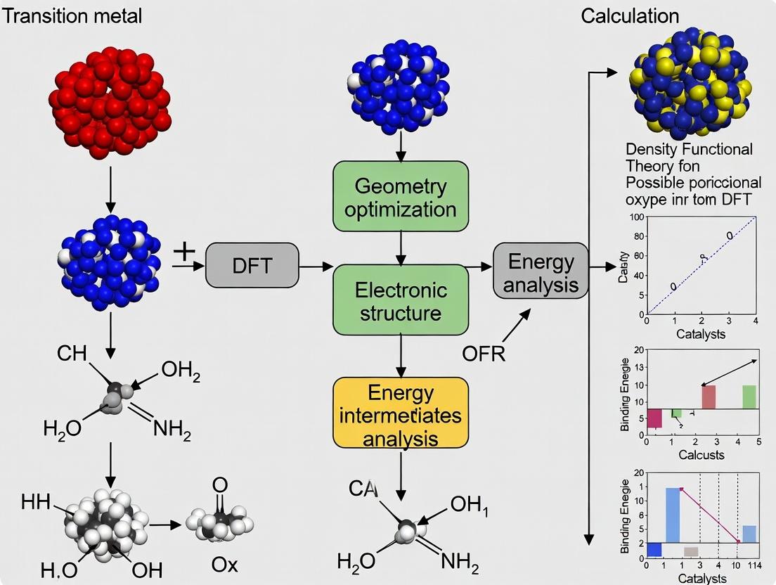
The oxygen reduction reaction (ORR) is the critical cathode reaction in biomedical energy devices such as implantable biofuel cells and biobatteries. These devices, which power advanced medical implants like pacemakers, neural stimulators, and drug delivery systems, require efficient, stable, and biocompatible ORR catalysts. Within the broader thesis on Density Functional Theory (DFT) calculation of ORR catalysts, this application note focuses on translating computational predictions of high-performance, non-platinum-group metal (non-PGM) catalysts into experimental validation and practical application for biomedical use. DFT research identifies key descriptors like oxygen adsorption energy, d-band center position, and charge transfer coefficients to screen materials such as metalloenzyme mimics, doped carbon nanostructures, and metal-organic frameworks (MOFs) before resource-intensive wet-lab experimentation.
Key Performance Metrics & Quantitative Data
Recent advances in non-PGM ORR catalysts, driven by DFT-guided design, show significant promise for biocompatible energy applications. The following table summarizes benchmark performance data for leading catalyst classes.
Table 1: Performance Metrics of DFT-Screened ORR Catalysts for Biomedical Applications
| Catalyst Class | DFT-Predicted Descriptor (e.g., ΔG*O, eV) | Onset Potential (vs. RHE) | Half-Wave Potential (E1/2, vs. RHE) | Kinetic Current Density (jk @ 0.8V vs. RHE, mA cm⁻²) | Selectivity for 4e⁻ Pathway (%) | Stability (Cycles/% Activity Retention) | Key Reference (Year) |
|---|---|---|---|---|---|---|---|
| Fe-N-C Single-Atom Catalysts | ΔG*OOH = 4.2 eV | 0.95 V | 0.82 V | 8.5 | >95% | 10,000 cycles / 92% | Wang et al. (2023) |
| Co-N4-doped Graphene | d-band center = -1.3 eV | 0.91 V | 0.78 V | 6.2 | ~90% | 5,000 cycles / 85% | Li et al. (2024) |
| Mn-based MOF (Biomimetic) | O₂ p-band center = -2.1 eV | 0.88 V | 0.75 V | 3.8 | >99% | 2,000 cycles / 95% | Chen & Park (2024) |
| Enzymatic (Laccase on CNT) | N/A | 0.85 V | 0.72 V | 1.5 | ~100% | 500 cycles / 70%* | Biomedical Devices Review (2023) |
*Enzymatic stability is often limited by operational lifetime under physiological conditions.
Experimental Protocols
Protocol 3.1: Electrochemical Synthesis and Characterization of DFT-Screened Fe-N-C Catalysts
Objective: To synthesize and electrochemically validate a Fe-N-C single-atom catalyst pre-identified by DFT as having near-optimal oxygen adsorption energy.
Materials: See "The Scientist's Toolkit" (Section 6).
Procedure:
- Catalyst Synthesis (Pyrolysis Route): a. Dissolve 2g of Zeolitic Imidazolate Framework-8 (ZIF-8) precursor and 50mg of Ferric Acetate in 20mL methanol. Sonicate for 30 min. b. Evaporate the solvent at 60°C under stirring to obtain a dry powder. c. Transfer the powder to a quartz boat and place in a tube furnace. Anneal under flowing Ar (200 sccm) at 900°C for 2 hours, then at 1000°C for 1 hour. d. Cool naturally to room temperature under Ar. The resulting black powder is acid-leached in 0.5M H₂SO₄ at 80°C for 8 hours to remove unstable metal particles. e. Filter, wash thoroughly with DI water, and dry overnight at 80°C to obtain the final Fe-N-C catalyst.
Electrochemical Ink Preparation: a. Weigh 5mg of catalyst and disperse in 950μL of a water/isopropanol (3:1 v/v) mixture and 50μL of 5 wt% Nafion solution. b. Sonicate the mixture in an ice bath for at least 60 minutes to form a homogeneous ink.
Rotating Disk Electrode (RDE) Fabrication: a. Polish a glassy carbon (GC) RDE tip (5mm diameter) sequentially with 1.0μm and 0.05μm alumina slurry on a microcloth. Rinse thoroughly with DI water. b. Pipette 10μL of the catalyst ink onto the mirror-polished GC surface and dry under ambient conditions to form a thin, uniform film (catalyst loading ~0.4 mg cm⁻²).
ORR Activity Measurement (Linear Sweep Voltammetry - LSV): a. Use a standard three-electrode cell: catalyst-coated RDE as working electrode, Pt wire as counter electrode, and Ag/AgCl (3M KCl) as reference electrode. All potentials are converted to the Reversible Hydrogen Electrode (RHE) scale. b. Purge the 0.1M KOH (or phosphate buffer saline for biomedical context) electrolyte with O₂ for at least 30 minutes. c. Perform cyclic voltammetry (CV) from 1.0 to 0.2 V vs. RHE at 50 mV s⁻¹ for 20 cycles to activate the catalyst. d. Record LSV curves from 1.1 to 0.2 V vs. RHE at a scan rate of 10 mV s⁻¹ and rotation speeds from 400 to 2025 rpm. e. Purge the cell with N₂ and record a background LSV under the same conditions for subtraction.
Data Analysis: a. Use the background-subtracted LSV curves at different rotations. b. Apply the Koutecky-Levich equation at various potentials to calculate the kinetic current (jk). c. Determine the electron transfer number (n) from the slope of K-L plots. An
nclose to 4 indicates a direct 4-electron pathway to H₂O, which is preferred. d. Extract the half-wave potential (E₁/₂) and onset potential from the LSV at 1600 rpm.
Protocol 3.2: In-Vitro Biocompatibility and Stability Testing for Implantable Device Integration
Objective: To assess the cytotoxicity and long-term electrochemical stability of the synthesized catalyst under simulated physiological conditions.
Procedure:
- Material Leachate Preparation: Sterilize catalyst pellets under UV light for 1 hour. Incubate in sterile Dulbecco's Modified Eagle Medium (DMEM) at a concentration of 1 mg mL⁻¹ for 72 hours at 37°C. Filter the supernatant through a 0.22μm membrane.
- Cell Viability Assay (ISO 10993-5): a. Culture L929 mouse fibroblast cells in DMEM with 10% fetal bovine serum. b. Seed cells in a 96-well plate at 10,000 cells/well and incubate for 24 hours. c. Replace the medium with 100μL of the material leachate (test group) or fresh medium (control group). Include a positive control (e.g., 1% Triton X-100). d. Incubate for 24 and 48 hours. Add 10μL of MTT reagent (5 mg mL⁻¹) to each well and incubate for 4 hours. e. Remove the medium, add 100μL of DMSO to solubilize formazan crystals, and measure absorbance at 570nm. Calculate cell viability relative to the control.
- Long-Term ORR Stability in PBS: Perform an accelerated stress test (AST) by cycling the catalyst-coated RDE in O₂-saturated PBS (pH 7.4) between 0.6 and 1.0 V vs. RHE at 100 mV s⁻¹ for 5,000-10,000 cycles. Periodically (e.g., every 1,000 cycles) record LSVs at 1600 rpm to monitor the loss in E₁/₂ and kinetic current.
Visualizations
DFT to Device Workflow for ORR Catalysts
ORR Reaction Pathways at Catalyst Surface
The Scientist's Toolkit: Research Reagent Solutions
Table 2: Essential Materials for ORR Catalyst Research & Testing
| Item | Function in Research | Example Product/ Specification |
|---|---|---|
| High-Purity Precursors | Source of metal and nitrogen/carbon for controlled catalyst synthesis. | ZIF-8 (Basolite Z1200), Ferric Acetate (≥99.99%), 1,10-Phenanthroline. |
| Nafion Perfluorinated Resin Solution | Binder and proton conductor for preparing catalyst inks for electrode coating. | 5 wt% in lower aliphatic alcohols (e.g., Sigma-Aldrich 274704). |
| Electrochemical Grade Solvents & Salts | Preparation of non-contaminated electrolytes for accurate potential measurement. | KOH pellets (99.99% trace metals basis), Isopropanol (HPLC grade). |
| Phosphate Buffered Saline (PBS) | Simulates physiological electrolyte for biomedical-relevant testing (pH 7.4). | Sterile, 1X, without calcium and magnesium. |
| Rotating Disk Electrode (RDE) System | Essential for measuring ORR kinetics by controlling oxygen diffusion. | Glassy Carbon tip (5mm), Pine Research or Metrohm rotator. |
| Reference Electrode (Ag/AgCl) | Provides a stable, known potential reference in aqueous electrochemistry. | Double-junction, filled with 3M KCl electrolyte. |
| MTT Cell Proliferation Assay Kit | Standard colorimetric method to assess catalyst cytotoxicity (biocompatibility). | ISO 10993-5 compliant kits. |
| Gas Regulation System | Precise purging of electrolyte with O₂ or N₂ for controlled ORR and baseline measurement. | Mass flow controllers with high-purity (≥99.999%) gas tanks. |
Within Density Functional Theory (DFT) studies of oxygen reduction reaction (ORR) catalysts, understanding the precise reaction mechanism is critical for predicting and optimizing catalyst performance. The two primary pathways—associative and dissociative—define how O₂ is activated and reduced on a catalyst surface. The identification and stability of reaction intermediates (e.g., OOH, *O, *OH) are central to these calculations, as they determine the thermodynamic overpotential. This application note details protocols for computational elucidation of these pathways, providing a practical guide for researchers integrating mechanistic DFT studies into broader catalyst development theses.
Associative Pathway
In the associative mechanism, molecular O₂ adsorbs on the catalyst surface (O₂) and is directly hydrogenated via proton-electron transfer before O-O bond scission. General Sequence: O₂(g) + * → *O₂ → *OOH → *O + *OH → 2OH → H₂O + *
Dissociative Pathway
In the dissociative mechanism, the O-O bond cleaves upon or immediately after adsorption, yielding two adsorbed oxygen atoms (O), which are then sequentially hydrogenated. General Sequence: O₂(g) + 2 → 2O → *O + *OH → 2OH → H₂O + *
Table 1: Comparative DFT-Calculated Thermodynamic Descriptors for ORR Pathways on Model Surfaces (Typical Values)
| Catalyst Model | Pathway | Rate-Determining Step | Calculated ΔG (eV) | Theoretical Overpotential η (V) | Key Intermediate Stability |
|---|---|---|---|---|---|
| Pt(111) | Associative | *O → *OH | ~0.80 | ~0.45 | *OOH weakly bound |
| Pt(111) | Dissociative | O₂ dissociation | ~1.50 | >1.0 | *O strongly bound |
| Fe-N-C Single-Atom | Associative | *O₂ + H⁺ + e⁻ → *OOH | ~0.75 | ~0.50 | *OOH critical intermediate |
| Co₃O₄(110) | Dissociative | 2*O formation | ~0.95 | ~0.70 | *O stable |
Note: Values are illustrative from literature; exact numbers depend on DFT functional, solvation model, and coverage.
Detailed Computational Protocols
Protocol: Determining the ORR Pathway via NEB Calculations
Objective: Identify the preferred pathway (associative vs. dissociative) by calculating activation barriers for O₂ dissociation and initial hydrogenation. Software: VASP, Quantum ESPRESSO, ORCA (with transition state tools). Workflow:
- System Setup: Optimize clean catalyst slab model (≥4 layers, 3×3 supercell minimum). Apply vacuum >15 Å. Fix bottom 1-2 layers.
- Initial & Final States:
- For Dissociation: Optimize O₂ (end-on or side-on) and 2O configurations.
- For Associative Step: Optimize *O₂ and *OOH configurations.
- NEB Calculation:
- Generate 5-7 images between initial and final states using IDPP or linear interpolation.
- Set convergence criteria: force < 0.05 eV/Å per atom.
- Use CI-NEB method with climbing image to locate the saddle point.
- Analysis: The pathway with the lower effective barrier (including thermodynamic considerations) is typically preferred. The dissociation barrier >> hydrogenation barrier suggests associative dominance.
Protocol: Free Energy Diagram Construction via Computational Hydrogen Electrode (CHE)
Objective: Construct the free energy profile for ORR at U=0 V and the equilibrium potential (1.23 V) to identify potential-determining steps. Workflow:
- Intermediate Optimization: Fully relax all intermediates (*O₂, *OOH, *O, *OH, H₂O).
- Electronic Energy Calculation: Perform high-precision, static calculation on each relaxed structure to obtain total electronic energy (E_DFT).
- Gibbs Free Energy Correction: Calculate vibrational frequencies to obtain zero-point energy (ZPE) and thermal corrections (T=298.15 K). Apply standard harmonic oscillator approximation.
- G ≈ EDFT + EZPE + ∫C_v dT - T*S
- Apply CHE Model:
- G(* + H⁺ + e⁻) = ½ G(H₂) at U=0 V vs. SHE.
- For potential U: G(U) = G(0V) - eU, where e is the elementary charge.
- Adjust the free energy of intermediates involving (H⁺+e⁻) transfer by -eU.
- Plot & Analyze: Plot G for each step at U=0V and U=1.23V. The step with the largest positive ΔG at 1.23V is the potential-determining step. The overpotential η = (max[ΔG])/e - 1.23 V.
Visualization of Mechanisms & Workflows
Diagram 1: Associative ORR Pathway (76 characters)
Diagram 2: Dissociative ORR Pathway (76 characters)
Diagram 3: DFT Workflow for ORR Mechanism Study (76 characters)
The Scientist's Toolkit: Key Research Reagent Solutions
Table 2: Essential Computational "Reagents" for ORR Mechanism DFT Studies
| Item / Software | Category | Primary Function in ORR Studies |
|---|---|---|
| VASP | DFT Code | Periodic slab calculations with PAW pseudopotentials; robust for metallic surfaces and NEB. |
| Quantum ESPRESSO | DFT Code | Open-source plane-wave code for periodic systems; suitable for transition metal oxides. |
| Gaussian/ORCA | DFT Code | Molecular cluster calculations; often used for modeling M-N-C single-atom catalysts. |
| PBE Functional | XC Functional | Standard GGA functional for structure optimization; baseline for catalysis studies. |
| RPBE/PBE-D3 | XC Functional | Adjusted for better adsorption energies; D3 corrects for dispersion forces in O₂/OOH. |
| CHE Model Script | Analysis Tool | Python/Matlab script to convert electronic energies to Gibbs free energy vs. potential. |
| VASPKIT/ASE | Analysis Toolkit | Automates post-processing (DOS, Bader charge) and workflow management. |
| solVASP or VASPsol | Implicit Solvation | Adds Poisson-Boltzmann implicit solvation to model aqueous electrochemical interface. |
Density Functional Theory (DFT) is the predominant computational quantum mechanical modeling method for investigating the electronic structure of atoms, molecules, and condensed phases, particularly within catalysis research. Its utility in modeling the Oxygen Reduction Reaction (ORR) lies in its ability to predict adsorption energies, reaction pathways, and electronic properties of catalyst surfaces at a fraction of the cost of higher-level theories. The core theorem, the Hohenberg-Kohn theorem, establishes that the ground state electron density uniquely determines all properties of a system. The Kohn-Sham equations then map the complex many-body problem onto a system of non-interacting electrons moving in an effective potential, which includes exchange-correlation effects.
For ORR catalyst research—critical for fuel cells and metal-air batteries—DFT enables the screening of materials (e.g., Pt alloys, M-N-C single-atom catalysts, perovskites) by calculating key descriptors such as the adsorption free energy of oxygen intermediates (OOH, *O, *OH). The scaling relations between these adsorption energies often dictate the catalytic activity, visualized via volcano plots.
Application Notes for ORR Catalyst Modeling
Key Calculational Descriptors and Quantitative Benchmarks
Successful modeling of ORR catalysts relies on calculating specific energetics. The following table summarizes the primary descriptors and typical target values for optimal Pt-based catalysts.
Table 1: Key DFT-Calculated Descriptors for ORR Catalyst Evaluation
| Descriptor | Definition | Optimal Value (Theoretical) | Role in ORR Activity |
|---|---|---|---|
| ΔG*OOH | Adsorption free energy of *OOH intermediate | ~3.6 eV | Directly related to ΔG*OH via scaling relation; defines the overpotential. |
| ΔG*O | Adsorption free energy of atomic *O | ~1.0 eV (relative to *OH) | Strongly correlates with metal-oxide formation energy. |
| ΔG*OH | Adsorption free energy of *OH intermediate | ~0.8 eV (vs. standard) | Often used as the primary activity descriptor; minima on volcano plots. |
| d-band center (εd) | Mean energy of the metal d-band relative to Fermi level | Downshift from pure Pt for alloys | Correlates with adsorbate binding strength; lower εd weakens binding. |
| Overpotential (η) | η = max[ΔG1, ΔG2, ΔG3, ΔG4]/e - 1.23 V | Minimum theoretical: ~0.3-0.4 eV | The key performance metric; derived from the free energy diagram. |
Standard Computational Workflow for ORR
A standard DFT protocol for studying an ORR catalyst involves several consecutive stages, from model construction to analysis.
Diagram 1: DFT Workflow for ORR Catalyst Screening
Detailed Experimental Protocols
Protocol: Calculation of Oxygen Adsorption Free Energy on a Pt(111) Surface
This protocol details the steps to compute the free energy of *OH adsorption, a critical descriptor.
Aim: To determine ΔG*OH on a Pt(111) slab model. Software: Vienna Ab initio Simulation Package (VASP) is used here, but principles apply to other DFT codes (Quantum ESPRESSO, CP2K).
Procedure:
- Slab Model Generation:
- Create a 3-5 layer periodic slab of Pt(111) with a vacuum layer of ≥15 Å in the z-direction.
- Use a p(3x3) or p(4x4) surface supercell to minimize adsorbate-adsorbate interactions.
- Fix the bottom 1-2 layers at their bulk positions to mimic the substrate.
Bulk & Clean Slab Reference:
- Perform a full geometry optimization of the Pt bulk unit cell to obtain the accurate lattice constant.
- Optimize the geometry of the clean slab. The total energy from this step is Eslab.
Adsorbate-Slab System Optimization:
- Place an *OH adsorbate on a preferred site (e.g., fcc hollow on Pt(111)).
- Fully relax the geometry of the adsorbate and the top 2-3 metal layers until forces are < 0.01 eV/Å. The total energy is Eslab+OH.
Reference Molecule Calculations:
- Place an isolated H2O molecule in a large cubic cell (≥10 Å side length). Optimize geometry to get EH2O.
- Perform a similar calculation for an isolated H2 molecule to get EH2.
Energy to Free Energy Correction:
- Perform vibrational frequency calculations on the optimized *OH-slabs and isolated H2O and H2 molecules.
- Calculate the zero-point energy (ZPE) and vibrational entropy (Svib) contributions at 298.15 K.
- Standard Correction Formula (Simplified): ΔG*OH = ΔE + ΔZPE - TΔS where ΔE = Eslab+OH - Eslab - (EH2O - 1/2 EH2)
- Include solvation effects via an implicit solvation model (e.g., VASPsol) for aqueous ORR conditions.
Analysis: Plot the free energy diagram for the 4-e- ORR pathway at U=0 V and U=1.23 V. The potential-determining step is identified from the largest positive ΔG.
Protocol: d-Band Center Analysis for Alloy Catalysts
Aim: To compute the d-band center of surface atoms in a Pt3Ni(111) alloy and correlate it with adsorption strength. Procedure:
- After the static SCF calculation of the clean surface (Step 3 in main workflow), calculate the Projected Density of States (PDOS).
- Extract the d-orbital projected DOS for the surface Pt atoms.
- Calculate the first moment (weighted average energy) of the d-projected DOS within a relevant energy window (e.g., -10 eV to Fermi level): εd = ∫{-∞}^{Ef} E * ρd(E) dE / ∫{-∞}^{Ef} ρ_d(E) dE
- Compare ε_d for Pt3Ni(111) with pure Pt(111). A downshift (more negative) typically indicates weakened adsorbate binding.
The Scientist's Toolkit: Research Reagent Solutions
Table 2: Essential Computational "Reagents" for DFT-Based ORR Research
| Item / Software | Category | Primary Function in ORR Modeling |
|---|---|---|
| VASP | DFT Code | Performs core electronic structure calculations using the PAW method. Industry standard for periodic systems. |
| Quantum ESPRESSO | DFT Code | Open-source alternative using plane-wave basis sets and pseudopotentials. |
| GPAW | DFT Code | Uses the Projector Augmented-Wave (PAW) method with real-space/grid numerical basis sets. |
| ASE (Atomic Simulation Environment) | Python Library | Scripting, setting up calculations, manipulating atoms, and analyzing results. Essential for automation. |
| Pymatgen | Python Library | Advanced materials analysis, generating input files, and robust phase diagram analysis. |
| Implicit Solvation Model (e.g., VASPsol) | Solvation Correction | Approximates the effect of an aqueous electrolyte on adsorbate energies, critical for ORR. |
| Nudged Elastic Band (NEB) | Transition State Finder | Locates minimum energy paths and saddle points for elementary reaction steps (e.g., O2 dissociation). |
| PBE / RPBE Functional | Exchange-Correlation Functional | Generalized Gradient Approximation (GGA) functionals for structure and adsorption energies. RPBE often better for adsorption. |
| HSE06 / SCAN Functional | Exchange-Correlation Functional | Higher accuracy functionals (hybrid, meta-GGA) for improved electronic properties and band gaps. |
Advanced Analysis: Free Energy Diagram Construction
The free energy diagram is the final, critical visualization. For ORR, the four proton-electron transfer steps are considered:
- O2(g) + H+ + e- → *OOH
- *OOH + H+ + e- → *O + H2O(l)
- *O + H+ + e- → *OH
- *OH + H+ + e- → * + H2O(l)
Diagram 2: ORR Free Energy Diagram at Equilibrium Potential
Diagram Interpretation: The highest point on the diagram (here at *OOH or *OH formation) determines the thermodynamic overpotential. An ideal catalyst has all steps at or below the thermodynamic potential line (1.23 eV below O2/H2O level at U=1.23 V).
Within the broader research of a thesis on DFT calculation for oxygen reduction reaction (ORR) catalysts, selecting an appropriate exchange-correlation (XC) functional is a fundamental and critical decision. The ORR, a key cathodic process in fuel cells and metal-air batteries, involves complex multi-electron/proton transfer steps (O₂ + 4H⁺ + 4e⁻ → 2H₂O). Accurately modeling adsorption energies of reaction intermediates (O, OH, OOH) on catalyst surfaces is paramount for predicting activity, often described via scaling relations and volcano plots. This application note details the use, protocols, and comparative analysis of three essential classes of functionals: the Generalized Gradient Approximation (GGA) functionals PBE and RPBE, and the more advanced hybrid functionals.
Core DFT Functionals: Theory and Application
PBE (Perdew-Burke-Ernzerhof)
A seminal GGA functional, PBE provides a significant improvement over LDA for solids and surfaces. It is computationally efficient and has been the workhorse for ORR catalyst screening, particularly for transition metals and their alloys. However, it is known to overbind adsorbates, which can systematically affect predicted adsorption energies and overestimate catalyst activities.
RPBE (Revised PBE)
A reparameterization of PBE specifically designed to improve the description of adsorption processes. RPBE corrects PBE's overbinding error, typically yielding more accurate chemisorption energies on metal surfaces. Its computational cost is identical to PBE, making it a preferred choice for more accurate GGA-level studies of ORR intermediates.
Hybrid Functionals (e.g., HSE06, B3LYP)
Hybrid functionals mix a portion of exact Hartree-Fock exchange with DFT exchange-correlation. They better account for electronic self-interaction error and are generally more accurate for systems with localized d-electrons and band gap predictions. HSE06, with its screened coulomb potential, is particularly popular in solid-state systems for its improved computational feasibility compared to full hybrids like B3LYP. They are crucial for studying non-metallic catalysts like single-atom sites in carbon matrices or metal oxides.
Table 1: Comparison of Essential DFT Functionals for ORR Studies
| Functional Class | Example | Key Feature for ORR | Typical Cost (Rel. to PBE) | Best Use Case in ORR Catalyst Research | Known Limitation |
|---|---|---|---|---|---|
| GGA | PBE | Robust, efficient; baseline functional. | 1.0x | High-throughput screening of metallic alloys & surfaces. | Overbinds adsorbates (e.g., O, OH). |
| GGA | RPBE | Corrects PBE overbinding for adsorption. | 1.0x | Accurate adsorption energetics on metal surfaces. | May underbind in some cases; still lacks exact exchange. |
| Hybrid | HSE06 | Includes exact exchange; better electronic structure. | 10-100x | Single-atom catalysts, oxides, materials with strong correlation. | Computationally expensive; parameter-dependent. |
| Hybrid | B3LYP | High accuracy for molecular systems. | 50-200x | Cluster models of active sites, molecular catalysts. | Less reliable for periodic metallic systems. |
Computational Protocol for ORR Free Energy Calculation
This protocol outlines the standard workflow for calculating ORR free energy diagrams using a slab model within the thesis's computational framework.
Step 1: System Geometry Optimization
- Functional Selection: Choose initial functional (PBE recommended for initial metallic system relaxation due to stability).
- Software: Use a plane-wave code (e.g., VASP, Quantum ESPRESSO) with PAW pseudopotentials.
- Parameters: Set plane-wave cutoff energy ≥ 400 eV. Use k-point mesh of (4x4x1) or denser for surface Brillouin zone sampling. Convergence criteria: energy change < 10⁻⁵ eV, forces < 0.02 eV/Å.
- Slab Model: Build a >15 Å vacuum layer to prevent periodic interaction. Fix bottom 2 layers of the slab.
Step 2: Adsorbate Optimization & Energy Calculation
- Model Intermediates: Place O, OH, and OOH adsorbates at high-symmetry sites (e.g., fcc, bridge) on the relaxed surface.
- Re-optimize: Optimize adsorbate+slab geometry with tighter convergence (forces < 0.01 eV/Å).
- Electronic Energy: Perform a final, accurate single-point energy calculation. Repeat this entire step with RPBE and/or a hybrid functional (e.g., HSE06) on the final PBE geometries for comparative analysis.
Step 3: Free Energy Correction Calculate the Gibbs free energy of reaction intermediates: G = E_DFT + ZPE + ∫C_p dT - TΔS.
- Vibrational Analysis: Perform frequency calculations on the adsorbates (frozen slab approximation) to obtain Zero-Point Energy (ZPE) and entropic contributions (S).
- Standard Conditions: Use tabulated values for H₂O(l) and H₂(g) to reference the electrochemical potential. Apply the computational hydrogen electrode (CHE) model: ΔG = ΔE_DFT + ΔZPE - TΔS + eU, where U is the applied bias.
Step 4: Activity Analysis
- Construct the free energy diagram for all four proton-electron transfer steps at U=0 V and at the theoretical limiting potential (U_L).
- Identify the potential-determining step (PDS) with the largest positive ΔG.
- Plot adsorption energy scaling relations (e.g., ΔGOH vs. ΔGOOH) to locate the catalyst on a volcano plot.
The Scientist's Toolkit: Essential Research Reagents & Computational Materials
Table 2: Key Computational "Reagents" for DFT-based ORR Studies
| Item / Software | Function in Research | Example / Note |
|---|---|---|
| Plane-wave DFT Code | Core engine for solving Kohn-Sham equations. | VASP, Quantum ESPRESSO, CASTEP, ABINIT. |
| Pseudopotential Library | Represents core electrons, reduces computational cost. | PAW (VASP), USPP, Norm-conserving PPs. |
| Catalyst Structure Database | Source of initial slab/model geometries. | Materials Project, OQMD, ICSD. |
| Adsorbate Database | Reference energies for gas-phase molecules. | NIST CCCBDB, computational references (e.g., O₂, H₂O). |
| Free Energy Scripts | Automates post-processing of DFT data to ΔG. | pymatgen, ASE (Atomic Simulation Environment), custom scripts. |
| High-Performance Computing (HPC) Cluster | Provides necessary computational resources. | Typically Linux-based CPU/GPU clusters. |
Visualized Workflows and Relationships
Diagram 1: DFT Functional Decision Workflow for ORR (76 chars)
Diagram 2: ORR Free Energy Landscape & Functional Effects (76 chars)
This document provides application notes and protocols for modeling electrochemical interfaces, specifically within the context of Density Functional Theory (DFT) research for Oxygen Reduction Reaction (ORR) catalysts. Accurately representing the solid-liquid interface under applied potential remains a significant challenge in computational electrochemistry.
Key Challenges:
- Explicit vs. Implicit Solvation: Balancing computational cost with an accurate description of solvent structure, hydrogen bonding, and ion distribution.
- Electrode Potential Control: Explicitly setting and stabilizing the electrode potential within a DFT simulation.
- Constant Potential Methods: Implementing methodologies where the system's charge, not its total number of electrons, is fixed to mimic a potentiostat.
- pH and Ion Specificity: Incorporating the effects of pH and specific cation/anion adsorption beyond simple electrostatic screening.
- Dynamic Stability: Assessing the stability of catalyst surfaces and adsorbates under realistic operating conditions (potential, solvent, ions).
Current Best Practices & Protocols
Protocol: Setting Up an Implicit Solvation Model for ORR Steps
This protocol outlines the use of an implicit solvation model (e.g., VASPsol, JDFTx) to study ORR intermediates on a Pt(111) surface.
Materials & Software:
- DFT code (e.g., VASP, Quantum ESPRESSO).
- Implicit solvation extension.
- Catalyst slab model (≥ 4 atomic layers, ≥ 3x3 surface unit cell).
- Pseudopotentials/Potential files.
Procedure:
- Geometry Optimization (Vacuum): Optimize the clean slab model in vacuum. Fix the bottom two layers.
- Solvent Integration: Enable the implicit solvation model. Key parameters include the solvent dielectric constant (e.g., ~78.4 for water), cavity formation surface tension, and the Debye length for ionic screening (set based on electrolyte concentration).
- ORR Intermediate Adsorption: Place ORR intermediates (*O₂, *OOH, *O, *OH) in various adsorption sites on the surface.
- Slab-Charge Neutralization: For charged systems, use a homogeneous background charge (compensating charge) or the implicit solvation model's charge compensation tool.
- Convergence: Re-optimize all geometries with the solvation model active. Ensure forces are converged (< 0.01 eV/Å) and total energy differences are stable with respect to k-point sampling and plane-wave cutoff.
Protocol: Explicit Solvent/Aqueous Interface with Hybrid MD-DFT
This protocol describes a more advanced setup using explicit water molecules and ab initio molecular dynamics (AIMD).
Procedure:
- Build the Aqueous Interface: Start with an optimized slab. Use molecular dynamics (classical or DFT-MD) to pre-equilibrate a layer of water molecules (≥ 3 monolayers) on the surface. Include counter-ions (e.g., H₃O⁺, OH⁻) to achieve desired pH.
- System Setup: Ensure the simulation cell has a vacuum layer (≥ 15 Å) above the water to prevent interactions between periodic images.
- AIMD Sampling: Perform a short AIMD simulation (NVT ensemble, ~330 K) to sample equilibrated solvent configurations. Use a time step of ~0.5-1.0 fs.
- Snapshot Analysis: Extract multiple statistically independent snapshots from the AIMD trajectory.
- Static DFT Calculation: Perform high-accuracy static DFT calculations on individual snapshots to compute adsorption energies of ORR intermediates. The final energy is an average over snapshots.
- Free Energy Correction: Apply zero-point energy and thermal corrections (often from vibrational analysis in a smaller model system) to obtain free energies (ΔG).
Protocol: Applying a Constant Electrochemical Potential
This protocol uses the Computational Hydrogen Electrode (CHE) method, the current standard for estimating potential-dependent reaction energies.
Procedure:
- Reference Potential: Define the reversible hydrogen electrode (RHE) at standard conditions (pH=0, pH₂=1 bar, U=0 V) as your potential reference.
- Calculate Reaction Free Energy: For an electrochemical step: A + (H⁺ + e⁻) → AH, the free energy change is ΔG = ΔE + ΔZPE - TΔS + eU.
- ΔE: DFT total energy difference.
- ΔZPE/TΔS: Difference in zero-point energy/entropy between products and reactants (obtained from vibrations).
- U: The applied potential vs. RHE.
- pH Adjustment: To model pH ≠ 0, add the correction term ΔGpH = kB * T * ln(10) * pH ≈ 0.059 * pH eV at 298 K.
- Free Energy Diagram: Construct a free energy diagram for the ORR pathway (O₂ → OOH → *O → *OH → H₂O) as a function of applied potential *U.
- Overpotential Calculation: The theoretical thermodynamic overpotential (η) is determined from the potential at which all elementary steps become exergonic.
Data Presentation: Key DFT Parameters & ORR Metrics
Table 1: Common DFT Settings for ORR Interface Modeling
| Parameter | Typical Value/Range | Functional/Role |
|---|---|---|
| XC Functional | RPBE, BEEF-vdW, SCAN, HSE06 | Determines accuracy of adsorption energies; meta-GGA/hybrids improve on GGA. |
| Solvent Model | Implicit (VASPsol), Explicit (~40-100 H₂O), Hybrid | Describes electrolyte environment; choice balances cost/accuracy. |
| Ionic Strength | Debye length ~3-10 Å in implicit models | Screens electrostatic interactions; models electrolyte concentration. |
| Slab Layers | 3-5 metal layers | Represents bulk electrode; bottom 1-2 layers fixed. |
| Vacuum Layer | >15 Å (explicit solvent), >10 Å (implicit) | Prevents periodic interaction between slabs. |
| k-point Sampling | Monkhorst-Pack, e.g., 4x4x1 for 3x3 cell | Integrates over Brillouin zone. |
Table 2: Calculated ORR Intermediate Adsorption Energies (ΔG in eV) on Pt(111) at U=0 V vs. RHE
| Intermediate | Adsorption Site | ΔG (GGA-PBE, Implicit Solvent) | ΔG (Meta-GGA, Explicit Solvent Avg.) | Notes |
|---|---|---|---|---|
| *OOH | Bridge/Top | ~0.80 - 1.00 | ~0.95 - 1.15 | Key for 4e⁻ vs. 2e⁻ pathway selectivity. |
| *O | FCC | ~1.50 - 1.80 | ~1.65 - 1.95 | Strongly bound; often the potential-determining intermediate. |
| *OH | FCC | ~0.30 - 0.50 | ~0.45 - 0.65 | Desorption as H₂O is final step. |
| O₂ (side-on) | Bridge | ~0.10 - 0.30 | N/A (dissociates) | Physisorbed state; often not stable in explicit solvent. |
Visualization of Methodologies
Title: Workflow for Modeling Electrochemical ORR Interfaces
Title: Constant Potential Scheme via Computational Hydrogen Electrode
The Scientist's Toolkit: Research Reagent Solutions
Table 3: Essential Computational "Reagents" for Electrochemical Interface DFT
| Item/Category | Example/Name | Function & Purpose |
|---|---|---|
| DFT Software | VASP, Quantum ESPRESSO, CP2K, GPAW | Core simulation engine for solving the electronic structure problem. |
| Solvation Module | VASPsol, JDFTx, SCCS (in QE) | Implements an implicit dielectric continuum to model solvent effects. |
| AIMD Engine | CP2K, VASP (MDALGO), NWChem | Performs ab initio molecular dynamics for explicit solvent sampling. |
| Exchange-Correlation Functional | BEEF-vdW, RPBE, SCAN, HSE06 | Defines the approximation for electron-electron interactions; critical for accuracy. |
| Pseudopotential Library | PSlibrary, GBRV, SG15 | Provides pre-tested pseudopotentials for efficient plane-wave calculations. |
| Post-Processing Tool | pymatgen, ASE, Vasppy | Scripts for analysis of energies, structures, and generation of free energy diagrams. |
| Reference Database | Materials Project, CatHub, NOMAD | Provides benchmark structures and energies for validation. |
| High-Performance Computing (HPC) | Local clusters, NSF/XSEDE, EU PRACE | Essential computational resource for running large-scale DFT/AIMD calculations. |
This application note details protocols for benchmarking electrocatalysts, specifically for the Oxygen Reduction Reaction (ORR), within the context of Density Functional Theory (DFT)-guided research. The core metrics are the thermodynamic overpotential (η) and the activity volcano plot, which are derived from adsorption free energies of key reaction intermediates. These energies serve as descriptors, enabling high-throughput computational screening and rational catalyst design.
Key Quantitative Data & Descriptors
Table 1: Common ORR Reaction Pathways and Descriptors (in Acidic Media)
| Pathway | Key Elementary Steps | Thermodynamic Descriptor | Ideal ΔG (eV) |
|---|---|---|---|
| Associative (4e⁻) | * + O₂ + H⁺ + e⁻ → OOH* OOH* + H⁺ + e⁻ → O* + H₂O O* + H⁺ + e⁻ → OH* OH* + H⁺ + e⁻ → H₂O + * | ΔG(OOH) - ΔG(OH) or ΔG(O*) | ΔG(OOH) = 4.22 eV ΔG(O) = 0 eV |
| Dissociative (4e⁻) | O₂ + 2* → 2O* O* + H⁺ + e⁻ → OH* OH* + H⁺ + e⁻ → H₂O + * | ΔG(O*) | ΔG(O*) = 0 eV |
Table 2: Benchmark Adsorption Free Energies & Overpotential for Model Surfaces
| Catalyst Surface | ΔG(O*) (eV) | ΔG(OH*) (eV) | ΔG(OOH*) (eV) | Theoretical η (V) | Experimental η (V) ~ |
|---|---|---|---|---|---|
| Pt(111) | -1.08 | 0.80 | 4.33 | 0.45 | 0.3-0.4 |
| Ir(111) | -0.55 | 1.12 | 4.27 | 0.56 | ~0.5 |
| Au(111) | 1.39 | 2.10 | 5.40 | 1.15 | >0.8 |
| "Ideal" Catalyst | 0.00 | 1.23 | 4.22 | 0.00 | N/A |
Detailed Experimental & Computational Protocols
Protocol 3.1: DFT Calculation of Adsorption Free Energies
Objective: Calculate the adsorption free energy (ΔG_ads) of intermediates (O, OH, OOH*) on a catalyst slab model.
Procedure:
- Geometry Optimization: Build a periodic slab model (≥ 4 layers, ≥ 3×3 unit cell). Optimize the clean slab geometry using a GGA-PBE functional until forces < 0.02 eV/Å.
- Intermediate Adsorption: Place the intermediate in various high-symmetry sites (e.g., atop, bridge, fcc/hcp hollow). Re-optimize all atoms in the adsorbate and top 2-3 catalyst layers.
- Electronic Energy Calculation: Perform a single-point energy calculation on the optimized adsorption system with a higher plane-wave cutoff and k-point density.
- Vibrational Frequency Analysis: Perform a vibrational frequency calculation for the adsorbed species (fixing the slab). Use harmonic approximation to obtain zero-point energy (ZPE) and vibrational entropy (S_vib) corrections.
- Free Energy Calculation: Compute ΔGads using: ΔGads = ΔEDFT + ΔZPE - TΔSvib + ΔGU + ΔGpH where ΔEDFT is the DFT energy difference, ΔGU accounts for electrode potential (U vs. SHE), and ΔGpH corrects for pH (≈ -kB T ln(10) × pH).
Protocol 3.2: Constructing the Activity Volcano Plot
Objective: Plot catalytic activity (log|j₀|) as a function of a single descriptor (e.g., ΔG(O) or ΔG(OH)).
Procedure:
- Define Scaling Relations: For a set of similar materials (e.g., transition metals), establish linear scaling relations: ΔG(OOH) = a × ΔG(OH) + b and ΔG(O) = c × ΔG(OH) + d. These reduce the multi-dimensional problem to one descriptor.
- Calculate Free Energy Diagrams: For each value of the descriptor, construct the free energy diagram for the ORR pathway at U = 0 V vs. SHE.
- Identify Potential-Determining Step (PDS): For each diagram, find the step with the largest positive ΔG. This is the PDS.
- Compute Theoretical Current: The theoretical exchange current density is approximated as: j₀ ∝ exp(-ΔGPDS / kB T), where ΔG_PDS is the free energy of the PDS at equilibrium potential (U=1.23 V).
- Plot the Volcano: On the x-axis, plot the descriptor value (e.g., ΔG(OH*)). On the y-axis, plot log|j₀| (or -ΔG_PDS). The peak corresponds to the optimal descriptor value.
Protocol 3.3: Calculating Thermodynamic Overpotential (η)
Objective: Determine the minimum overpotential required to make all ORR steps downhill in free energy.
Procedure:
- Build Diagram at U=1.23V: Using the calculated ΔG_ads values, plot the free energy of each reaction intermediate at the theoretical equilibrium potential (1.23 V). Correct energies using ΔG = -eU for steps involving an electron.
- Apply an External Potential (U): Systematically lower the applied potential (e.g., to 1.0 V, 0.8 V) by shifting the free energy of electron-proton transfer steps (H⁺ + e⁻).
- Find Onset Potential: Identify the potential (U_onset) at which the free energy diagram becomes entirely downhill (all ΔG < 0 for forward steps).
- Calculate η: η = 1.23 V - U_onset. This is the thermodynamic overpotential.
Visualization of Concepts & Workflows
Diagram 1: DFT-Based Catalyst Benchmarking Workflow
Diagram 2: Free Energy Diagram and Overpotential
The Scientist's Toolkit: Research Reagent Solutions
Table 3: Essential Computational & Experimental Materials for ORR Benchmarking
| Item/Category | Function & Explanation |
|---|---|
| DFT Software (VASP, Quantum ESPRESSO, GPAW) | Performs first-principles electronic structure calculations to determine adsorption energies, electronic properties, and reaction pathways. |
| Catalyst Slab Models (e.g., from Materials Project CIFs) | Atomic structure files used as the computational representation of the catalyst surface for DFT simulations. |
| Pseudopotentials/PAW Potentials | Define the interaction between valence electrons and atomic cores, critical for accuracy in plane-wave DFT calculations. |
| Vibrational Frequency Code (e.g., VASP, ASE) | Calculates vibrational modes of adsorbed intermediates to obtain Zero-Point Energy and entropy corrections for free energy. |
| Reference Electrode (e.g., RHE - Reversible Hydrogen Electrode) | Experimental standard for measuring electrode potential. Computational work scales all potentials to the RHE scale. |
| Rotating Ring-Disk Electrode (RRDE) | Key experimental apparatus for measuring ORR activity (disk current) and selectivity for H₂O₂ (ring current). |
| Nafion Membrane & Proton-Conducting Electrolyte (e.g., 0.1 M HClO₄) | Provides proton conduction in the electrochemical cell, mimicking fuel cell operating conditions. |
| High-Surface Area Carbon Support (e.g., Vulcan XC-72) | Used experimentally to disperse and stabilize nanoparticle catalysts for uniform thin-film electrode preparation. |
| Scaling Relation Databases | Curated datasets of adsorption energies across materials, enabling rapid descriptor-based activity prediction. |
A Step-by-Step DFT Workflow for ORR Catalyst Design and Screening
Within the broader thesis on Density Functional Theory (DFT) calculation for oxygen reduction reaction (ORR) catalyst research, the atomic-scale structural model is the foundational computational entity. This application note details the protocols for constructing and analyzing three dominant catalyst archetypes: extended surfaces, nanoclusters, and single-atom structures. These models serve to probe structure-activity relationships, with the ultimate goal of designing high-performance, cost-effective catalysts for applications such as fuel cells and metal-air batteries.
Model Construction Protocols
Extended Surface Models (Slabs)
- Purpose: To model the catalytic behavior of bulk crystalline materials, terraces, and low-index facets (e.g., Pt(111), IrO₂(110)).
- Protocol:
- Obtain the bulk crystal structure (e.g., from the Materials Project or ICSD database). Optimize the bulk unit cell using DFT to obtain the equilibrium lattice constant.
- Cleave the crystal along the desired Miller indices (hkl) using a structure visualization tool (e.g., VESTA).
- Build a slab supercell with a thickness of 3-5 atomic layers. The thickness must be verified by convergence testing of the property of interest (e.g., adsorption energy).
- Introduce a vacuum layer of at least 15 Å in the direction perpendicular to the surface to prevent spurious interactions between periodic images.
- Terminate the bottom 1-2 layers, fixing their atomic positions to mimic the bulk substrate. Allow the top 2-3 layers and adsorbates to relax during calculations.
- For surface coverage studies, create a p(2x2) or larger supercell to model lower adsorbate coverages.
Nanocluster Models
- Purpose: To model nanoparticles (1-3 nm) where quantum size effects and a high proportion of edge/corner atoms dominate reactivity.
- Protocol:
- Geometry Generation: Use known structural motifs (e.g., cuboctahedron, icosahedron, decahedron) or employ global optimization algorithms (e.g., genetic algorithms, basin hopping) interfaced with empirical potentials to find low-energy isomers.
- Size Selection: Construct clusters with precise atom counts (e.g., Pt₅₅, Au₁₄₇) to represent specific "magic number" geometries.
- Initial Optimization: Perform a preliminary geometry optimization using a lower-level theory or force field.
- DFT Setup: Place the cluster in a cubic box with a vacuum margin of at least 10 Å from any atom to the box boundary. No atoms are fixed. Use a higher density k-point grid (e.g., Gamma-centered 2x2x2) or the Gamma-point only for larger clusters.
- Charge State: Apply an appropriate charge (neutral, anionic, cationic) based on the intended chemical environment. Include implicit solvation or explicit counterions if modeling charged states in solution.
Single-Atom Catalyst (SAC) Models
- Purpose: To model isolated metal atoms dispersed on a support (e.g., graphene, C₂N, metal oxide), maximizing atom utilization.
- Protocol:
- Support Preparation: Construct a periodic model of the support material (e.g., a 4x4 supercell of graphene). Ensure sufficient lateral size to prevent interaction between periodic images of the single atom.
- Active Site Creation:
- For carbon-based supports, create a defect site (e.g., single/double vacancy) or use a functional group (e.g., pyrrolic N) as an anchoring point.
- For oxide supports, model a specific surface termination and identify a stable adsorption site (e.g., on top of oxygen, bridging two metal cations).
- Metal Atom Deposition: Place a single transition metal atom (e.g., Fe, Co, Pt) at the intended anchoring site.
- Stability Check: Calculate the binding/cohesive energy to ensure the metal atom is thermodynamically stable against aggregation. Perform ab initio molecular dynamics (AIMD) at elevated temperatures (e.g., 500 K) for a short duration (5-10 ps) to test kinetic stability.
Key Computational Analysis Workflows
Title: DFT Workflow for ORR Reaction Energy Profiling
Research Reagent Solutions (Computational Toolkit)
| Item / Software | Function in Catalyst Modeling |
|---|---|
| VASP / Quantum ESPRESSO | Core DFT software for performing electronic structure, geometry optimization, and molecular dynamics calculations. |
| GPAW / CP2K | DFT codes using plane-wave/pseudopotential and Gaussian basis sets, efficient for large systems and hybrid functionals. |
| ASE (Atomic Simulation Environment) | Python library for setting up, manipulating, running, and analyzing atomistic simulations; essential for workflow automation. |
| pymatgen / custodian | Libraries for advanced materials analysis, generating input files, and robust job management with error correction. |
| VESTA / Ovito | Visualization software for constructing crystal slabs, viewing charge density, and analyzing trajectory/coordination data. |
| BEEF-vdW / SCAN | Advanced exchange-correlation functionals that include van der Waals corrections, crucial for accurate adsorption energies. |
| CHELPG / Bader | Methods for performing charge population analysis (e.g., Hirshfeld, Bader) to estimate atomic charges in catalysts. |
Quantitative Data for ORR on Representative Models
Table 1: Comparison of Calculated ORR Thermodynamic Overpotential (η, in V) on Various Catalyst Models. (Note: Example data based on representative literature values. Actual values depend on specific DFT functional, solvation model, and coverage.)
| Catalyst Model | Active Site | Key Intermediate | ΔGOOH* (eV) | ΔGO* (eV) | ΔGOH* (eV) | η (V) |
|---|---|---|---|---|---|---|
| Pt(111) Surface | Pt terrace | *OOH, *O, *OH | 4.20 | 3.20 | 0.80 | 0.45 |
| Pt₇₉ Cluster | Pt edge | *OOH, *O, *OH | 4.05 | 3.05 | 0.70 | 0.30 |
| Fe-N₄/C SAC | Fe-N₄ | *OOH, *OH | 3.98 | - | 0.85 | 0.38 |
| Co₃O₄(110) Surface | Co3+ | *OOH, *O, *OH | 4.35 | 3.40 | 1.10 | 0.80 |
Protocol for Calculating the ORR Free Energy Diagram
- Step 1: System Optimization. Optimize the geometry of the clean catalyst model and each adsorbed intermediate (*O₂, *OOH, *O, *OH, and *H₂O) independently.
- Step 2: Frequency Calculation. Perform vibrational frequency calculations on all optimized structures to obtain zero-point energy (ZPE) and entropic (TΔS) corrections. Treat adsorbates in the harmonic approximation and use ideal gas/standard liquid values for gas-phase H₂ and liquid H₂O.
- Step 3: Free Energy Correction. Compute the free energy correction, Gcorr = ZPE + ∫CvdT - TΔS, for each species.
- Step 4: Free Energy Assembly. Calculate the Gibbs free energy of each step (G = EDFT + Gcorr). The chemical potential of (H⁺ + e⁻) is referenced to ½ H₂ at standard conditions. Apply a potential correction: G(U) = G(0V) - neU, where n is the number of electrons transferred and U is the applied potential.
- Step 5: Overpotential Determination. Identify the potential-determining step (PDS) as the step with the largest positive ΔG at the equilibrium potential (U=1.23 V). The thermodynamic overpotential is η = max[ΔG1-4]/e - 1.23 V.
Title: Four-Electron ORR Pathway on Catalyst Surface
Within the broader thesis on Density Functional Theory (DFT) research for oxygen reduction reaction (ORR) catalysts, the adsorption energies of oxygen-containing intermediates—atomic oxygen (O), hydroxyl (OH), and hydroperoxyl (*OOH)—are established as fundamental descriptors. Their accurate calculation is paramount for predicting catalyst activity and stability, often correlated via scaling relationships and activity volcanoes. This application note provides protocols for computing these energies, forming the quantitative basis for rational catalyst design.
Key Principles and Scaling Relationships
The ORR on catalyst surfaces (e.g., Pt, alloys, single-atom catalysts) typically proceeds through a four-electron pathway. The binding strengths of *O, *OH, and *OOH are intrinsically linked, a phenomenon described by linear scaling relationships. This constrains their relative energies and determines the overpotential.
Quantitative Scaling Relationship Data (Representative Values):
| Descriptor Pair | Typical Scaling Slope (DFT-GGA) | Typical Intercept (eV) | Remarks |
|---|---|---|---|
| ΔEOOH vs. ΔEOH | ~1.0 | ~3.2 ± 0.2 eV | Highly consistent across metals. |
| ΔEO vs. ΔEOH | ~2.0 | ~0.1 ± 0.2 eV | Slope often ~2; varies with site/geometry. |
| ΔEOOH vs. ΔEO | ~0.5 | Derived | Not independent; follows from above. |
Theoretical Overpotential (η) Estimation: The theoretical overpotential is determined by the maximum difference in free energy (ΔG) among the reaction steps (at U=0 V). The ideal catalyst has ΔG for all steps equal to 1.23 eV. The descriptor ΔGOH – ΔGOOH is often used as a direct activity indicator.
Protocol: Calculating Adsorption Energies via DFT
The following protocol details the steps for obtaining consistent and comparable adsorption energy values.
System Setup & Geometry Optimization
- Supercell & Vacuum: Construct a periodic slab model (e.g., 3-5 atomic layers) with a sufficient vacuum region (>15 Å) to prevent periodic image interactions. Use a p(3x3) or larger surface unit cell to minimize adsorbate-adsorbate interactions.
- k-point Sampling: Use a Monkhorst-Pack grid (e.g., 3x3x1 for p(3x3)) for Brillouin zone integration. Test for convergence.
- Computational Parameters:
- Functional: Select an appropriate exchange-correlation functional. PBE-GGA is standard but tends to over-bind. RPBE, BEEF-vdW, or hybrid functionals (HSE) can improve accuracy at higher computational cost.
- Pseudopotential/PAW: Use project-augmented wave (PAW) potentials or ultrasoft pseudopotentials from standardized libraries (e.g., VASP, Quantum ESPRESSO).
- Cutoff Energy: Set plane-wave kinetic energy cutoff (e.g., 400-500 eV for VASP). Confirm energy convergence.
- Convergence Criteria: Force convergence < 0.01-0.02 eV/Å; energy convergence < 10^-5 eV.
- Optimization: Optimize the clean slab, fixing the bottom 1-2 layers. Then, place the adsorbate (*O, *OH, *OOH) on the desired site (e.g., top, bridge, fcc/hcp hollow) and optimize the full geometry.
Energy Calculation & Adsorption Energy Formula
Calculate the total energy for the optimized systems:
- E(slab+ads): Total energy of the slab with the adsorbed species.
- E(slab): Total energy of the clean, optimized slab.
- E(H₂O): Total energy of a gas-phase water molecule.
- E(H₂): Total energy of a gas-phase hydrogen molecule.
The adsorption energies (ΔE) are calculated with reference to H₂O and H₂ to avoid errors from O₂ dissociation, using the Computational Hydrogen Electrode (CHE) framework:
- ΔEOH = E(slab+OH) – E(slab) – [E(H₂O) – ½ E(H₂)]
- ΔEO = E(slab+O) – E(slab) – [E(H₂O) – E(H₂)]
- ΔEOOH = E(slab+OOH) – E(slab) – [2 E(H₂O) – 3/2 E(H₂)]
Note: These formulas give adsorption energies directly comparable to the free energies at standard conditions (T=298K, p=1 bar, U=0 V vs. SHE).
Free Energy Correction
To compare with experiment, convert electronic energies (ΔE) to Gibbs free energies (ΔG) at 298 K: ΔG = ΔE + ΔZPE – TΔS + ΔGU + ΔGpH
- ΔZPE: Zero-point energy correction (calculate from vibrational frequencies).
- TΔS: Entropic contribution. For adsorbed species, vibrational entropy is small. For gas-phase H₂O and H₂, use standard tabulated values.
- ΔG_U: Effect of electrode potential: –eU, where n is the number of electrons transferred in that step.
- ΔGpH: Correction for pH: –kB * T * ln(10) * pH.
For standard analysis (U=0, pH=0), only ΔZPE and TΔS are needed.
Validation & Benchmarking
- Reference Systems: Benchmark calculated adsorption energies for Pt(111) against well-established literature values (see table below).
- Convergence Tests: Systematically test k-points, slab thickness, vacuum size, and cutoff energy.
- Magnetic Moments: For systems with unpaired electrons (e.g., *O on some surfaces), ensure correct spin polarization is applied.
Benchmark Adsorption Energies (PBE, Pt(111), approximate):
| Adsorbate | Binding Site | ΔE (eV) | ΔG (eV, U=0, pH=0) |
|---|---|---|---|
| *O | fcc hollow | ~-3.9 | ~-3.8 |
| *OH | top | ~-2.2 | ~-2.0 |
| *OOH | fcc hollow (O-down) | ~-3.3 | ~-2.9 |
The Scientist's Toolkit: Research Reagent Solutions
| Item | Function in DFT ORR Research |
|---|---|
| VASP / Quantum ESPRESSO / GPAW | Core DFT simulation software for solving the Kohn-Sham equations and computing electronic structure. |
| ASE (Atomic Simulation Environment) | Python library for setting up, manipulating, running, and analyzing atomistic simulations. Essential for workflow automation. |
| PBE / RPBE / BEEF-vdW Functional | Exchange-correlation functionals. PBE is standard; RPBE reduces over-binding; BEEF-vdW includes dispersion and enables error estimation. |
| Catalysis-Hub.org / NOMAD | Online databases for sharing, comparing, and benchmarking calculated catalytic properties, including adsorption energies. |
| VASPKIT / pymatgen | Post-processing toolkits for analyzing DFT output files, extracting energies, densities of states, and more. |
| Phonopy | Software for calculating vibrational frequencies from finite displacements, required for ZPE and entropy corrections. |
Visual Workflow & Relationships
Title: DFT Workflow for ORR Descriptor Calculation
Title: ORR Pathway & Linked Descriptors
Determining Reaction Free Energy Diagrams and Potential-Dependent Steps
Within the broader thesis on developing Density Functional Theory (DFT)-based screening protocols for oxygen reduction reaction (ORR) catalysts, determining accurate reaction free energy diagrams is paramount. These diagrams map the thermodynamic landscape of the multi-step ORR, identifying potential-dependent steps—those elementary reactions whose free energy change is a function of the applied electrode potential. This application note details the computational protocols for constructing these diagrams, essential for predicting catalyst activity via the potential-determining step and the associated theoretical overpotential.
Theoretical Framework & Key Equations
The ORR in acidic media proceeds via multiple possible pathways. The associative pathway is commonly represented as:
- O₂ + (H⁺ + e⁻) + * → OOH*
- OOH* + (H⁺ + e⁻) → O* + H₂O
- O* + (H⁺ + e⁻) → OH*
- OH* + (H⁺ + e⁻) → H₂O + * where * denotes a surface site.
The computational hydrogen electrode (CHE) model is used to account for the chemical potential of a proton-electron pair (H⁺ + e⁻) at a given potential U versus the standard hydrogen electrode (SHE). The free energy change ΔG of a potential-dependent electrochemical step is calculated as: ΔG(U) = ΔE + ΔZPE - TΔS + neU where ΔE is the DFT-calculated reaction energy, ΔZPE and ΔS are changes in zero-point energy and entropy, T is temperature (298.15 K), n is the number of protons/electrons transferred in the step, and U is the applied potential.
Research Reagent Solutions (The Computational Toolkit)
| Item/Category | Function in ORR DFT Studies |
|---|---|
| DFT Software (VASP, Quantum ESPRESSO) | Performs electronic structure calculations to solve for total energies of adsorbate-surface systems. |
| Exchange-Correlation Functional (RPBE, BEEF-vdW) | Approximates quantum mechanical electron-electron interactions. RPBE is common for adsorption; BEEF-vdW includes dispersion. |
| Projector Augmented-Wave (PAW) Pseudopotentials | Represents core electrons, reducing computational cost while maintaining accuracy for valence states. |
| Slab Model Catalyst Surface | A periodic supercell representation of the catalyst's active crystal facet (e.g., Pt(111), Fe-N₄-doped graphene). |
| Vibrational Frequency Calculator | Computes Hessian matrix to derive zero-point energies (ZPE) and entropic corrections for adsorbed species. |
| Computational Hydrogen Electrode (CHE) Script | Automates the application of the potential-dependent correction (neU) to DFT energies to construct free energy diagrams. |
Protocol 1: Calculating Adsorption Free Energies
- 1.1 Geometry Optimization: Build a periodic slab model with sufficient vacuum (>15 Å). Optimize the clean surface structure. Place the adsorbate (O₂, OOH, O, OH*) at plausible sites (e.g., atop, bridge, hollow). Run spin-polarized DFT to fully relax all atoms except the bottom 2-3 fixed slab layers.
- 1.2 Energy Extraction: Extract the final total energy (E_DFT) for the optimized adsorbate-surface system.
- 1.3 Vibrational Analysis: Perform frequency calculations on the adsorbed state and corresponding gas-phase molecules (O₂, H₂O, H₂). Use harmonic approximation to compute ZPE and entropy (S). Correct for gas-phase reference states (e.g., ½ H₂ for H*).
- 1.4 Free Energy Calculation: Compute the adsorption free energy at standard conditions (U=0 V) as: Gads = EDFT + E_ZPE - TS. For species involving H (like OOH), reference to H₂O and H₂ using the CHE.
Protocol 2: Constructing Potential-Dependent Free Energy Diagrams
- 2.1 Define Pathway: Choose a reaction pathway (e.g., 4-e⁻ associative). List all intermediate states (e.g., , OOH, O, OH, *).
- 2.2 Compute ΔG at U=0: For each elementary step, calculate ΔG(U=0) using energies from Protocol 1.
- 2.3 Apply Potential Correction: For steps transferring n protons/electrons, compute ΔG(U) = ΔG(U=0) + ne * U, where ne is typically 1 for ORR steps. This linearly shifts the energy of that intermediate relative to others.
- 2.4 Identify Potential-Dependent Step: At a given applied potential U, the step with the largest positive ΔG(U) is the potential-determining step (PDS). The theoretical limiting potential U_L is the potential where the ΔG of the PDS becomes zero.
- 2.5 Diagram Generation: Plot the free energy of each intermediate (y-axis) versus the reaction coordinate (x-axis) for multiple potentials (e.g., 0 V, U_L, 1.23 V).
Data Presentation: ORR Free Energy Analysis for Pt(111) at U = 0.8 V vs. RHE
Table: DFT-Calculated Free Energy Components for ORR Intermediates on Pt(111) (RPBE functional). Values in eV.
| Intermediate | E_DFT (eV) | ZPE Correction (eV) | -TΔS (298K) (eV) | G_ads (U=0) (eV) | Relative G at U=0.8V (eV) |
|---|---|---|---|---|---|
| * (clean surface) | 0.00 | 0.00 | 0.00 | 0.00 | 0.00 |
| OOH* | -3.52 | 0.48 | 0.35 | -2.69 | -1.89 |
| O* | -4.45 | 0.12 | 0.10 | -4.23 | -4.23 |
| OH* | -2.84 | 0.35 | 0.20 | -2.29 | -1.49 |
| H₂O (l) | -14.22 | 0.57 | 0.67 | -12.98* | -12.98 |
Note: H₂O(l) energy is used as a reference. The step O → OH* (ΔG = 2.74 eV at U=0) is the PDS at 0 V. At U=0.8V, the step OH* → H₂O (ΔG = 0.99 eV) becomes the PDS, determining the activity.*
Visualization: ORR Free Energy Diagram Construction Workflow
Title: Workflow for DFT-based free energy diagram construction.
Visualization: Conceptual Free Energy Diagram at Different Potentials
Title: ORR free energy diagrams at zero and limiting potentials.
Application Notes
This document details the application of high-throughput, automated Density Functional Theory (DFT) screening for discovering novel catalysts for the Oxygen Reduction Reaction (ORR). Within the broader thesis on DFT Calculation for Oxygen Reduction Reaction Catalysts Research, this approach is crucial for rapidly navigating vast chemical spaces, such as transition metal alloys, doped carbon nanostructures, and single-atom catalysts, to identify promising candidates with optimal adsorption energies for O₂ and intermediates (OOH, O, OH*).
Core Principles and Data Outputs
High-throughput DFT automation involves scripting frameworks (e.g., Python with ASE, FireWorks) to manage the workflow: candidate generation, input file creation, job submission to compute clusters, error recovery, and automated parsing of results. Key screening descriptors for ORR include the adsorption free energy of key intermediates (ΔGOOH*, ΔGO, ΔG_OH), with the ideal catalyst exhibiting a thermoneutral ΔGOH* of ~0.80 eV. The overpotential (ηORR) is derived from scaling relations.
Quantitative data from a representative screening study of 120 M@N₄-C single-atom catalysts (M = Transition Metal) is summarized below.
Table 1: High-Throughput DFT Screening Results for Select M@N₄-C Catalysts
| Catalyst | ΔG_OOH* (eV) | ΔG_O* (eV) | ΔG_OH* (eV) | η_ORR (V) | Projected Activity (log(j₀)) |
|---|---|---|---|---|---|
| Fe@N₄-C | 4.23 | 2.10 | 0.85 | 0.45 | -2.1 |
| Co@N₄-C | 4.35 | 2.98 | 1.12 | 0.72 | -4.8 |
| Mn@N₄-C | 3.98 | 1.85 | 0.65 | 0.25 | -1.5 |
| Ni@N₄-C | 4.52 | 3.45 | 1.45 | 1.05 | -7.3 |
| Ideal | 4.22 | N/A | 0.80 | 0 | ∞ |
Table 2: Computational Parameters & Performance Metrics
| Parameter | Specification | Purpose |
|---|---|---|
| DFT Code | VASP, Quantum ESPRESSO | Electronic structure calculation engine |
| Functional | RPBE, with D3 dispersion correction | Describes exchange-correlation; balances accuracy/speed for adsorption |
| k-points | 4x4x1 Monkhorst-Pack | Brillouin zone sampling for slab models |
| Cutoff Energy | 520 eV (Plane-wave basis) | Balances computational cost and precision |
| Convergence Criteria | 1e-5 eV (electronic), 0.02 eV/Å (ionic) | Ensures reliable energy and geometry |
| SCF Solver | DIIS with Kerker mixing | Accelerates self-consistent field convergence |
| Throughput | ~150-200 calculations/day (100-core cluster) | Measures screening capacity |
Experimental Protocols
Protocol 1: Automated Workflow for ORR Catalyst Screening
Objective: To automatically compute ORR activity descriptors (ΔGOOH*, ΔGO, ΔG_OH) for a library of candidate catalysts.
Materials & Software:
- Workflow Manager: FireWorks or AiiDA.
- Atomistic Simulation Environment (ASE).
- DFT Code (e.g., VASP license).
- High-Performance Computing (HPC) cluster with job scheduler (SLURM/PBS).
- Candidate structure database (e.g., Materials Project, OQMD, or custom-generated).
Procedure:
- Candidate Generation & Initialization:
- Input a list of candidate compositions and structures (e.g., slab models for surfaces, cluster models for SACs).
- Use ASE to generate initial POSCAR files. For surfaces, ensure a vacuum layer >15 Å.
- Workflow Definition (FireWorks Script):
- Define FireWork tasks: Structure Optimization → Static Calculation → Adsorption Energy Calculations.
- For each adsorption intermediate (OOH, O, OH), create a child FireWork that modifies the optimized clean surface to add the adsorbate in a plausible configuration.
- DFT Calculation Parameters:
- Relaxation: Use the ISIF=2 tag (VASP) to relax ions and cell shape. Set EDIFFG = -0.02.
- Static Run: From relaxed geometry, perform a single-point calculation with tighter convergence (EDIFF=1E-6) and denser k-grid (6x6x1) for accurate energy.
- Adsorbate Energy Reference: Run separate calculations for H₂O(l) and H₂(g) to establish references. Use the standard hydrogen electrode (SHE) correction: ΔG = ΔE + ΔZPE - TΔS + 0.059*pH.
- Job Submission & Monitoring:
- Launch the FireWorks workflow. The manager will create input files, submit jobs to the HPC queue, detect completion, and parse outputs.
- Monitor queue status and failed jobs via the FireWorks web GUI.
- Data Parsing & Analysis:
- Upon completion, a parsing script extracts total energies, calculates adsorption energies, and computes ΔG values.
- Apply scaling relations to plot the volcano curve and calculate ηORR = max(ΔGOOH, ΔGO + 3.2eV, ΔGOH* + 2.46eV)/e - 1.23V.
- Output results to a centralized database (e.g., MongoDB) for further analysis.
Protocol 2: Explicit Free Energy Calculation for OOH* Intermediate
Objective: To compute the Gibbs free energy of adsorption for the OOH intermediate (ΔG_OOH) on a given catalyst surface.
Procedure:
- Optimize Clean Surface & OOH-Adsorbed Surface:
- Follow relaxation steps in Protocol 1 for both the clean slab and the slab with an OOH molecule adsorbed in a candidate site (e.g., atop, bridge).
- Calculate Adsorption Energy (ΔEOOH*):
- ΔEOOH* = E(slab+OOH) - E(slab) - [E(H₂O) + 1/2 E(H₂)].
- Use calculated energies from static runs.
- Compute Zero-Point Energy (ZPE) and Entropic (TΔS) Corrections:
- Perform vibrational frequency calculations on the adsorbed OOH* and free molecules (H₂O, H₂, O₂).
- Use the Hessian matrix (finite differences) to compute vibrational modes.
- ZPE = (1/2)Σhν_i. TΔS (298.15 K) is computed from partition functions.
- Typical Corrections: ZPEOOH* ≈ 0.42 eV; TΔSOOH* ≈ 0.40 eV. The gas-phase references are also corrected.
- Apply SHE Correction:
- ΔGOOH* = ΔEOOH* + ΔZPE - TΔS + 0.059 * pH (assume pH=0 for acidic ORR).
- Validation:
- Ensure the O-O bond length in *OOH is ~1.45-1.50 Å, consistent with superoxo/peroxo character.
- Check the adsorption configuration is a local minimum via vibrational analysis (no imaginary frequencies).
Visualizations
Title: High-Throughput DFT Screening Workflow
Title: ORR 4-e⁻ Pathway on Catalyst Surface
The Scientist's Toolkit: Research Reagent Solutions
Table 3: Essential Computational Materials & Tools
| Item/Reagent | Function/Benefit in High-Throughput DFT Screening |
|---|---|
| VASP License | Industry-standard DFT software for accurate periodic boundary condition calculations on surfaces and solids. |
| ASE (Atomic Simulation Environment) | Python library for setting up, manipulating, running, and analyzing atomistic simulations; core for workflow automation. |
| FireWorks Workflow Manager | Open-source code for defining, managing, and executing complex computational workflows across HPC resources. |
| Materials Project API | Database access for initial crystal structures, properties, and prototype generation for screening libraries. |
| Pymatgen | Python library for robust analysis of materials data, generation of input files, and post-processing of results. |
| High-Performance Computing Cluster | Essential hardware for parallel execution of thousands of computationally intensive DFT calculations. |
| Pseudopotential Libraries (e.g., PAW_PBE) | Pre-verified, standardized pseudopotentials essential for consistent and accurate DFT energy calculations. |
| MongoDB Database | NoSQL database system for storing, querying, and managing the large volumes of structured and unstructured data output from screening. |
Application Notes
Within the broader thesis on accelerating oxygen reduction reaction (ORR) catalyst discovery via DFT, computational modeling of three distinct material classes—alloys, doped carbons, and single-atom catalysts (SACs)—is fundamental. These notes detail their comparative computational treatment, performance metrics, and integration into a predictive research workflow.
1. Alloy Catalysts: DFT modeling focuses on surface segregation, adsorption site modulation, and strain effects. The primary descriptor is the d-band center (εd). Alloying shifts the εd relative to pure metals, optimizing *O and *OH adsorption energies. Pt-based alloys (e.g., Pt₃Ni, PtCo) are benchmark systems. Recent studies highlight high-entropy alloys (HEAs) as a complex but promising class for exploration.
2. Doped Carbon Materials: These are modeled as metal-free catalysts, where heteroatoms (N, B, S, P) are incorporated into graphene sheets. The critical descriptors are the charge density distribution and spin density on the dopant atoms. N-doped carbons, particularly graphitic and pyridinic N configurations, are most studied. DFT calculates the free energy diagrams for the 4e⁻ ORR pathway, identifying potential-determining steps.
3. Single-Atom Catalysts (SACs): This class bridges homogeneous and heterogeneous catalysis. M-Nₓ (M=Fe, Co, Mn; x=4 common) motifs on N-doped carbon are the archetype. DFT modeling is essential for determining the metal center's oxidation state, coordination environment, and stability against leaching and aggregation. The ORR activity is strongly correlated with the adsorption energy of OH (ΔGOH), following a volcano plot relationship.
Table 1: Key DFT-Calculated Descriptors & Benchmark Performance for ORR Catalysts
| Material Class | Primary Activity Descriptor | Typical DFT-Calculated ΔG*OOH (eV) | Optimal ΔG*OH (eV) | Theoretical Overpotential η (V) |
|---|---|---|---|---|
| Pt(111) (Benchmark) | d-band center (ε_d ≈ -2.5 eV) | ~4.2 | ~0.8 | ~0.45 |
| Pt₃Ni(111) | Shifted ε_d (more negative) | ~3.8 | ~0.6 | ~0.3 |
| Fe-N₄ SAC | ΔG*OH on Fe site | ~3.5 | ~0.5 | ~0.35 |
| Pyridinic N-Carbon | Spin density on C adjacent to N | ~4.5 | N/A (different pathway) | ~0.5 |
Table 2: Computed Stability Metrics for SACs
| SAC Site | Formation Energy (eV) | Metal Cohesive Energy Difference (eV) | Dissolution Potential (V vs. RHE) |
|---|---|---|---|
| Fe-N₄ | -3.2 | -4.1 (Fe in SAC vs. bulk Fe) | 1.1 |
| Co-N₄ | -2.9 | -3.8 | 1.3 |
| Mn-N₄ | -2.5 | -3.2 | 0.9 |
Experimental Protocols
Protocol 1: DFT Workflow for ORR Free Energy Diagram Calculation Objective: To compute the free energy profile for the 4e⁻ ORR pathway on a catalyst surface.
- Structure Optimization: Build a periodic slab model (≥4 atomic layers) with a vacuum layer >15 Å. Use VASP or Quantum ESPRESSO. Relax all atoms until forces < 0.01 eV/Å.
- Adsorbate Placement: Place relevant intermediates (*O₂, *OOH, *O, *OH) at all symmetry-inequivalent high-symmetry sites (top, bridge, hollow).
- Energy Calculation: Perform spin-polarized calculations with a PBE+U or hybrid (HSE06) functional. Use a plane-wave cutoff >400 eV and dense k-point mesh. Include van der Waals corrections (DFT-D3).
- Free Energy Correction: Calculate vibrational frequencies to obtain zero-point energy (ZPE) and entropy (S) corrections. Apply the Computational Hydrogen Electrode (CHE) model: ΔG = ΔE + ΔZPE - TΔS + neU, where U is the potential vs. RHE.
- Analysis: Identify the most stable adsorption site for each intermediate. Plot the free energy diagram at U=0 V and the equilibrium potential (1.23 V). The potential-determining step (PDS) is the step with the largest positive ΔG.
Protocol 2: Ab Initio Molecular Dynamics (AIMD) for SAC Stability Assessment Objective: To evaluate the thermodynamic stability of a SAC under operational conditions.
- Initial Configuration: Place the optimized SAC model in a 3x3 or larger supercell with explicit water molecules (≥30 H₂O).
- Equilibration: Run an NVT ensemble using a Nosé-Hoover thermostat at T=300 K for 5-10 ps with a 1 fs timestep. Use a lower accuracy electronic convergence threshold (~10⁻⁴ eV) for efficiency.
- Production Run: Continue AIMD simulation for 15-20 ps. Monitor the metal-N bond distances and coordination number.
- Analysis: Calculate the radial distribution function (RDF) between the metal center and surrounding O/N atoms. Plot bond distance as a function of simulation time to check for dissociation.
Visualizations
Title: DFT Workflow for ORR Catalyst Modeling
Title: ORR Free Energy Pathway & Key Metrics
The Scientist's Toolkit: Research Reagent Solutions
Table 3: Essential Computational Tools & Resources for DFT-based ORR Research
| Item / Software | Function / Purpose |
|---|---|
| VASP / Quantum ESPRESSO | Primary DFT engines for periodic boundary condition calculations (energy, electronic structure, geometry optimization). |
| PBE, RPBE, HSE06 | Exchange-correlation functionals. PBE for general screening, HSE06 for accurate band gaps and energetics. |
| Computational Hydrogen Electrode (CHE) | A method to calculate reaction free energies at applied potentials. Core to ORR modeling. |
| VASPKIT / pymatgen | Scripting toolkits for high-throughput calculation setup, job management, and post-processing of DFT data. |
| Atoms-in-Molecules (AIM) / Bader | Charge analysis codes to determine electron transfer and oxidation states of metal centers in SACs. |
| Materials Project / NOMAD | Databases for obtaining initial crystal structures, comparing formation energies, and benchmarking results. |
| ASE (Atomic Simulation Environment) | Python framework for setting up, running, and analyzing atomistic simulations across different DFT codes. |
In Density Functional Theory (DFT) studies of Oxygen Reduction Reaction (ORR) catalysts, the accurate modeling of the electrochemical environment is critical. The thesis context focuses on bridging the gap between pristine surface calculations and real operating conditions in fuel cells or metal-air batteries. Explicitly modeling every solvent molecule is computationally prohibitive. Implicit solvation models, particularly those employing the Poisson-Boltzmann (PB) equation, provide a powerful alternative by treating the solvent as a continuous dielectric medium. This approach incorporates essential effects such as solvation energy, ion distribution (via the Boltzmann term), and the impact of applied electric fields, which are paramount for simulating the electrode potential at the solid-liquid interface in ORR.
Core Theoretical Framework & Quantitative Data
The Poisson-Boltzmann Equation
The nonlinear PB equation is the cornerstone of implicit electrolyte models:
∇ ⋅ [ε(r)∇φ(r)] = -4π [ρf(r) + ρmobile(r, φ)]
where ε(r) is the spatially dependent dielectric constant, φ(r) is the electrostatic potential, ρ_f(r) is the fixed charge density (e.g., from the catalyst), and ρ_mobile is the charge density of mobile ions in solution, given by the Boltzmann distribution.
Key Implicit Solvation Models for DFT
Different DFT software packages implement variants of the PB model. Key parameters and their typical values are summarized below.
Table 1: Comparison of Implicit Solvation Models in DFT Codes for ORR Studies
| Model Name | DFT Code(s) | Dielectric Profile (ε) | Ion Distribution | Key Parameters for ORR | Typical Solvation Energy Accuracy (for ions) |
|---|---|---|---|---|---|
| VASPsol | VASP | Smooth transition: εin to εwater (~78.4) | Linearized PB | Effective surface tension (σ), Debye length (κ⁻¹) | ±0.1 - 0.3 eV |
| SCCS | Quantum ESPRESSO | Self-consistent continuum solvation | Linearized PB | Solvent radius, cavity surface tension | ±0.05 - 0.2 eV |
| CANDLE | JDFTx | Multi-scale model combining PB and classical DFT | Nonlinear PB | Multiple cavity parameters, ion sizes | ±0.05 eV |
| COSMO | Various (ADF, ORCA) | Conductor-like screening model | Not included (conductor) | Radii for atomic spheres | ±0.1 - 0.4 eV (less accurate for electrolytes) |
| PySCF | PySCF | Smooth cavity model | Linearized PB | Solvent probe radius, quadratic cavity surface | ±0.1 eV |
Table 2: Typical Simulation Parameters for ORR Catalyst Studies (Pt(111) in Acidic Medium)
| Parameter | Symbol | Typical Value | Rationale / Effect on ORR Calculations |
|---|---|---|---|
| Bulk Solvent Dielectric Constant | ε_s | 78.4 (H₂O) | Models bulk water screening. |
| Inner Dielectric Constant | ε_in | 1-10 | Represents catalyst/adsorbate polarizability. |
| Ionic Strength | I | 0.1 - 1.0 M | Simulates electrolyte concentration (e.g., 0.1 M HClO₄). |
| Debye Length (at 0.1 M, 298K) | κ⁻¹ | ~9.6 Å | Screening length; affects potential decay. |
| Electrode Potential Reference | U | vs. SHE or RHE | Applied via a constant potential term (φ) in PB. |
| Cavity Surface Tension | σ | 0.5 - 1.5 mN/m | Corrects for cavitation energy; impacts adsorption energies. |
Application Notes for ORR Pathway Analysis
Calculating Adsorption Free Energies with Solvation
The key descriptor for ORR activity is the adsorption free energy of intermediates (O, OH, OOH*). The solvation correction is crucial:
ΔGads,solv = EDFT(ads/slab) - EDFT(slab) - EDFT(ads,g) + ΔG_solv
where ΔG_solv is computed as the difference in solvation free energy between the adsorbed state and the gas-phase species, obtained from a PB calculation on the DFT charge density.
Incorporating the Electric Field
The applied electrode potential is simulated by introducing a background counter-charge (ρ_ext) or by directly solving the PB equation under a constant potential boundary condition. This shifts the electrostatic potential in the simulation cell, directly affecting the stability of charged transition states in the ORR mechanism (O₂ + 4(H⁺ + e⁻) → 2H₂O).
Experimental Protocols
Protocol 1: Setting Up a VASPsol Calculation for ORR on a Pt(111) Slab
Objective: To compute the solvation-corrected adsorption energy of OH* on Pt(111) at 0.9 V vs. RHE.
Software: VASP 6.x with VASPsol module.
Steps:
- Geometry Optimization (Vacuum):
- Build your Pt(111) 3x3 slab with 4 layers (2 bottom fixed) and a ≥15 Å vacuum.
- Optimize the geometry of the clean slab and the slab with OH* adsorbed.
- Standard DFT settings: PBE functional, PAW potentials, 400 eV cutoff, k-points (e.g., 4x4x1). Converge forces < 0.02 eV/Å.
Single-Point Energy with Implicit Solvation:
- Use the optimized structures.
- In the
INCARfile, activate VASPsol and set key parameters: - Run a single-point energy calculation. The output (
OSZICAR) gives the total free energy including solvation contributions.
Post-Processing:
- Extract total energies:
E(slab+OH,solv)andE(slab,solv). - Calculate the binding energy:
E_bind,solv = E(slab+OH,solv) - E(slab,solv) - 0.5*E(H2O,g) + 0.5*[ΔG_H2O(g->l) + kT ln(10)*pH*e]. Account for the H₂O reference state and pH/potential via the Computational Hydrogen Electrode (CHE) model.
- Extract total energies:
Protocol 2: Performing a Constant-Potential Calculation with JDFTx/CANDLE
Objective: To solve the nonlinear PB equation under an applied potential for an ORR intermediate.
Software: JDFTx.
Steps:
- Input File Preparation (
infile):- Specify the DFT functional, geometry, and plane-wave cutoff.
- Define the implicit solvent:
- Apply a constant potential:
- Execution:
- Run
jdftx -i input.in. The solver self-consistently updates the electron density and the electrolyte potential.
- Run
- Analysis:
- Examine the output for the free energy (
F). - Use the tool
jdftx-analyzeto extract the electrostatic potential profile across the interface, verifying the potential drop.
- Examine the output for the free energy (
Visualizations
Title: Workflow for Implicit Solvation in ORR DFT Calculations
Title: Implicit Solvation Model at the Electrochemical Interface
The Scientist's Toolkit: Research Reagent Solutions & Essential Materials
Table 3: Essential Computational "Reagents" for PB/Implicit Solvation in ORR DFT
| Item / Software Module | Function in ORR Catalyst Simulation | Key Considerations |
|---|---|---|
| VASPsol Module | Adds implicit solvation and linearized PB to VASP. | Efficient for periodic metals; parameters (SIGMAK, LAMBDAD_K) need calibration. |
| JDFTx with CANDLE | Solves joint DFT + nonlinear PB for liquids. | Handles non-linear ion response and constant potential directly; steeper learning curve. |
| Quantum ESPRESSO + Environ | Provides SCCS and PB solvers. | Highly customizable cavity; good for complex electrolytes. |
| PySCF | Python-based DFT with PB solver. | Excellent for prototyping, scripting workflows, and analyzing potential profiles. |
| Reference Data Sets (e.g., S22, water adsorption) | For benchmarking solvation model accuracy. | Critical to test parameter sets on known systems before ORR catalysts. |
| CHE Scripts | Automates correction of DFT energies to Gibbs free energies at given U, pH. | Must be integrated with the solvation energy output. |
| Debye Length Calculator | Converts ionic strength (I) to screening length κ⁻¹. | Essential for setting realistic electrolyte conditions (κ⁻¹ = √(ε₀ε_r kT / 2e²I)). |
Solving Common DFT Challenges in ORR Simulations: Accuracy and Efficiency
1. Introduction & DFT Thesis Context In Density Functional Theory (DFT) studies of the Oxygen Reduction Reaction (ORR) on electrocatalyst surfaces, a persistent challenge is the systematic "overbinding" of oxygenated intermediates (O, *OH, *OOH). This error, inherent to generalized gradient approximation (GGA) and meta-GGA functionals, skews adsorption free energy (ΔG) calculations, leading to inaccurate predictions of overpotentials and activity trends via scaling relations. This document details functional selection strategies and *a posteriori correction schemes, framed within a thesis focused on achieving predictive accuracy for novel ORR catalyst discovery.
2. Quantitative Comparison of Functionals & Corrections Table 1: Performance of Select DFT Functionals for ORR Intermediate Adsorption on Pt(111)
| Functional | Type | Avg. Error vs. Exp. (eV) | Description of Overbinding Tendency | Computational Cost |
|---|---|---|---|---|
| PBE | GGA | ~0.5 - 1.0 | Severe overbinding of *O and *OH. | Low (Baseline) |
| RPBE | GGA | ~0.3 - 0.6 | Revised for reduced overbinding. | Low |
| BEEF-vdW | GGA+ | ~0.2 - 0.4 | Includes van der Waals and error estimation. | Moderate |
| SCAN | meta-GGA | ~0.1 - 0.3 | Improved for diverse bonds, but may still overbind. | High |
| HSE06 | Hybrid | ~0.05 - 0.2 | Mixes exact HF exchange, reduces self-interaction error. | Very High |
| PBE+U | GGA+U | Variable | For transition metal oxides; U parameter tunes 3d states. | Moderate-High |
Table 2: Common *A Posteriori Correction Schemes*
| Scheme | Core Principle | Key Parameter(s) | Typical Magnitude of Correction (eV) | Applicability |
|---|---|---|---|---|
| Linear Scaling | Linear correlation between *O and *OH binding. | Scaling constant (α) from reference data. | -0.3 to -0.6 per *O | Late transition metals. |
| Solvation Correction | Explicit/implicit model for H₂O stabilization of OH/OOH. | Dielectric constant, solvation model. | -0.2 to -0.5 | All aqueous-phase ORR. |
| Potential of Zero Charge (PZC) | Aligns DFT potential to the standard hydrogen electrode (SHE). | Work function, PZC of slab model. | ±0.1 - 0.3 | All electrochemical systems. |
| Bayesian Error Estimation (BEE) | Uses ensemble of functionals (BEEF-vdW) to quantify uncertainty. | Ensemble variance. | Provides error bars ±0.1-0.2 | Best with BEEF-vdW functional. |
3. Detailed Experimental Protocols
Protocol 3.1: Benchmarking Adsorption Energies with Hybrid Functional Accuracy (Tier-1 Protocol) Objective: Compute accurate benchmark adsorption energies for O, *OH on a well-defined surface (e.g., Pt(111)) using a hybrid functional. *Steps:
- Slab Construction: Build a 3-4 layer p(3x3) slab model with ≥15 Å vacuum. Fix bottom 1-2 layers.
- Geometry Optimization (GGA): Pre-optimize clean slab and adsorbate structures using PBE functional and a medium plane-wave cutoff (400 eV). Use a 3x3x1 k-point mesh.
- Single-Point Hybrid Calculation: Using the PBE-optimized geometries, perform a single-point energy calculation with the HSE06 functional. Increase cutoff to 500 eV. Use a denser k-point mesh (e.g., 5x5x1).
- Energy Calculation: Compute adsorption energy: Eads = E(slab+ads) - Eslab - E(gas molecule). For *OH, reference is H₂O and H₂ (½H₂O + ½H₂).
- Free Energy Correction: Apply zero-point energy, enthalpy, and entropy corrections from vibrational frequency calculations (PBE level) to obtain ΔG_ads.
Protocol 3.2: Applying Linear Scaling Correction (LSC) for High-Throughput Screening Objective: Rapidly correct PBE-calculated adsorption energies for a series of alloy catalysts. Steps:
- Reference Data Curation: Compile experimental *O or *OH binding energies OR high-level computational benchmarks (from Protocol 3.1) for 3-5 reference systems (e.g., Pt(111), Pd(111), Ni(111)).
- PBE Calculation: Compute PBE-level *O adsorption energies for the same reference systems.
- Determine Scaling Constant: Plot ΔEO(PBE) vs. ΔEO(reference). Perform linear regression: ΔEO(corrected) = α * ΔEO(PBE) + β. Extract α (~0.8-0.9) and β.
- Correct High-Throughput Data: For all new candidate materials screened with PBE, apply the scaling relation: ΔEO(corrected) = α * ΔEO(PBE) + β.
- Propagate to ΔG: Use scaled ΔEO to construct the ORR free energy diagram via scaling relations (ΔGOH ≈ ΔG_O + constant).
Protocol 3.3: Implicit Solvation Correction for OH and *OOH *Objective: Incorporate solvation stabilization for final ORR intermediates. Steps:
- Functional & Solver Selection: Use a functional compatible with your implicit solvation model (e.g., PBE with VASPsol).
- Vacuum Calculation: Optimize the slab with the adsorbate (*OH or *OOH) in vacuum. Compute energy E_vac.
- Solvated Calculation: Re-run the single-point energy calculation with the implicit solvation model activated. Use default dielectric constant for water (ε=80). Compute energy E_solv.
- Calculate Solvation Correction: ΔEsolv = Esolv - E_vac. (Typical value: -0.3 to -0.5 eV for *OH).
- Apply Correction: ΔGsolv-corrected = ΔGvac + ΔE_solv.
4. Visualization of Workflows & Relationships
Title: DFT Workflow for ORR Catalyst Screening with Corrections
Title: Root Causes of DFT Oxygen Overbinding Error
5. The Scientist's Toolkit: Research Reagent Solutions
Table 3: Essential Computational Materials & Software for ORR DFT Studies
| Item / Solution | Function / Role | Example (Not Endorsement) |
|---|---|---|
| DFT Software Suite | Core engine for electronic structure calculations. | VASP, Quantum ESPRESSO, GPAW. |
| Pseudopotential Library | Represents core electrons, defines basis set accuracy. | PAW potentials (VASP), SSSP library. |
| Implicit Solvation Module | Models electrolyte environment to stabilize charged/polar intermediates. | VASPsol, JDFTx, CANDLE solvation. |
| Phonon Calculation Code | Computes vibrational frequencies for ZPE and thermal corrections. | Phonopy, DFPT implementations. |
| Workflow Management Tool | Automates high-throughput calculation and data extraction. | AiiDA, ASE, pymatgen. |
| Error Estimation Ensemble | Quantifies uncertainty in DFT-predicted energies. | BEEF-vdW ensemble. |
| Reference Benchmark Database | Provides experimental/high-level data for validation and scaling. | CatApp, Materials Project, NOMAD. |
Within Density Functional Theory (DFT) research on oxygen reduction reaction (ORR) catalysts, achieving accurate results is contingent upon careful convergence of key computational parameters. The central challenge lies in balancing numerical accuracy with the prohibitive cost of modeling large, complex systems like transition metal-N-doped graphene or perovskite surfaces. This document outlines application notes and protocols for managing the trade-offs between k-point sampling, electronic/geometric convergence criteria, and model size, ensuring reliable predictions of catalytic activity (e.g., overpotential, adsorption energies) at a feasible computational cost.
Quantitative Convergence Benchmarks
The following tables summarize standard convergence targets and their typical impact on the computed properties of ORR intermediates (OOH, *O, *OH).
Table 1: k-point Sampling Convergence for Common ORR Catalyst Models
| Catalyst Model Type | Initial Sampling (Γ-centered) | Converged Sampling | ∆Eads(O*) Error (eV) | Typical System Size (Atoms) | Relative CPU Time |
|---|---|---|---|---|---|
| Metal(111) Slab (4-layer) | 3x3x1 | 11x11x1 | >0.1 | 40-60 | 1.0 (Baseline) |
| Nanoparticle (~1nm) | Γ-point only | 2x2x2 | ~0.15 | 80-150 | 2.5 |
| N-doped Graphene (4x4 supercell) | 2x2x1 | 5x5x1 | <0.05 | 50-70 | 1.2 |
| Perovskite Surface (2x2) | 2x2x1 | 6x6x1 | >0.2 | 100-150 | 3.0 |
Table 2: Energy Cutoff & SCF Convergence Criteria Impact
| Parameter | Loose Setting | Tight Setting | Effect on ORR Free Energy Diagram (ΔGmax) | Computational Cost Increase |
|---|---|---|---|---|
| Plane-wave Cutoff (eV) | 400 (for C,N,O) | 550 (for C,N,O) | Shift up to ~0.1 eV | ~2.5x |
| SCF Energy Tolerance | 10-5 eV | 10-6 eV | < 0.03 eV | ~1.5x |
| Force Convergence | 0.05 eV/Å | 0.01 eV/Å | Critical for OOH/OH binding | ~2.0x (Ionic steps) |
| k-points (Metal slabs) | (4x4x1) | (12x12x1) | Can reverse overpotential trend if under-converged | ~5.0x |
Experimental Protocols for Convergence Testing
Protocol 2.1: Systematic k-point Convergence for Surface Models
Objective: Determine the k-point mesh density where the adsorption energy of a key ORR intermediate (e.g., *O) changes by less than 0.02 eV.
- Model Preparation: Construct a pristine, optimized p(2x2) or p(3x3) surface slab (e.g., Pt(111), Fe-N-C monolayer) with ≥15 Å vacuum.
- Initial Calculation: Perform a single-point energy calculation using a moderate k-point mesh (e.g., 3x3x1 for slabs).
- Iterative Refinement: Increase the k-point density symmetrically (e.g., 4x4x1, 6x6x1, 8x8x1, 11x11x1). Use the same optimized geometry and all other computational parameters (cutoff, pseudopotential, XC functional).
- Data Collection: Record the total energy of the clean surface and the surface with the adsorbed intermediate for each mesh.
- Analysis: Plot ∆Eads versus the inverse of the k-point mesh density (or total number of k-points). The converged value is where the curve plateaus.
Protocol 2.2: Balancing Model Size and Sampling for Nanoparticle Catalysts
Objective: Assess the trade-off between increasing nanoparticle size (better model) and the possibility of using Γ-point-only sampling (lower cost).
- System Series: Generate a series of increasingly larger nanoparticle or cluster models (e.g., Pt13, Pt55, Pt147).
- Two-Pronged Test: a. For each model size, perform a Γ-point-only calculation. b. For the smallest and largest model, perform a full k-point convergence test (see Protocol 2.1).
- Benchmark Property: Calculate the adsorption energy of *OH. Compare the Γ-point result for the large model to the fully k-point-converged result of the small model.
- Decision Point: Identify the model size where Γ-point sampling yields adsorption energies within 0.05 eV of a converged k-point result for a key property.
Visualization of Convergence Workflow & Trade-offs
Title: DFT Convergence Decision Workflow for ORR Catalysts
Title: Core Trade-offs in DFT Computational Parameters
The Scientist's Toolkit: Key Research Reagent Solutions
Table 3: Essential Computational "Reagents" for ORR Catalyst DFT Studies
| Item (Software/Code) | Primary Function in ORR Research | Key Consideration for Cost-Accuracy Trade-off |
|---|---|---|
| VASP | Plane-wave DFT code for periodic systems; standard for slab & nanoparticle catalysts. | Efficient PAW pseudopotentials and parallel k-point sampling are crucial for large models. |
| Quantum ESPRESSO | Open-source plane-wave DFT code. | Allows flexibility in basis set truncation and solver choices to manage cost. |
| GPAW | DFT code using real-space grids or plane waves. | Linear-scaling methods can reduce cost for very large, sparse systems like doped carbons. |
| ASE (Atomic Simulation Environment) | Python framework for setting up, running, and analyzing DFT calculations. | Essential for automating convergence tests (Protocols 2.1, 2.2). |
| Pymatgen | Python library for materials analysis. | Used for generating k-point meshes, analyzing densities of states, and managing workflows. |
| SSAdNDP/LOBSTER | Bonding analysis & electronic structure tools. | Used post-convergence to understand active sites, but requires dense k-grids for accuracy. |
| AiiDA | Workflow management and computational provenance. | Critical for reproducing complex convergence studies and managing the parameter trade-off space. |
| Benchmark Databases (CatMAP, Materials Project) | Repositories of calculated adsorption energies and properties. | Provide reference points to validate your own convergence protocols and initial parameters. |
Addressing Spin Polarization and Magnetic Moments in Transition Metal Catalysts
Application Notes
Spin polarization and magnetic moments are critical electronic structure properties governing the activity and selectivity of transition metal (TM) catalysts, particularly for multi-electron transfer reactions like the Oxygen Reduction Reaction (ORR). Within Density Functional Theory (DFT) research on ORR catalysts, accounting for these magnetic properties is essential for accurate predictions of adsorption energies, reaction pathways, and overpotentials. This document provides protocols for calculating and analyzing these properties for TM complexes, surfaces, and nanoparticles.
Key Principles:
- Spin Polarization: The imbalance between spin-up and spin-down electron densities. In TM catalysts, this leads to net magnetic moments and significantly affects d-orbital energies, thereby modifying ligand binding strengths.
- Magnetic Moment: The total net magnetic moment (in Bohr magnetons, μB) is a primary descriptor. For ORR, the magnetic state of the active site influences the spin state of adsorbed O₂ and OOH* intermediates, impacting the mechanistic pathway (associative vs. dissociative).
- DFT+U & Hybrid Functionals: Standard Generalized Gradient Approximation (GGA) functionals often underestimate electron localization. A Hubbard U correction (DFT+U) or hybrid functionals (e.g., HSE06) are frequently required for accurate description of strongly correlated d-electrons in oxides and certain TM complexes.
Recent Findings (2023-2024): Live search data indicates a surge in studies focusing on spin-state engineering for single-atom catalysts (SACs) on graphene and carbon nitride supports. The magnetic moment of the central TM ion (e.g., Fe, Co, Ni) is shown to correlate linearly with the activation barrier for O-O bond cleavage. Furthermore, research highlights the role of spin-polarized charge transport in magnetic catalyst substrates (e.g., ferromagnetic alloys) in enhancing ORR kinetics.
Table 1: Calculated Magnetic Moments and ORR Overpotentials for Selected Single-Atom Catalysts (M-N₄-C)
| TM Center | DFT Functional | Magnetic Moment (μB) | Preferred O₂ Adsorption Mode | Limiting Potential (V) | Overpotential η (V) |
|---|---|---|---|---|---|
| Fe | PBE+U (U=4.0) | 3.2 | Side-on, bridge | 0.80 | 0.45 |
| Co | PBE+U (U=3.0) | 2.1 | End-on | 0.75 | 0.50 |
| Ni | PBE+U (U=6.0) | 1.8 | End-on | 0.68 | 0.57 |
| Mn | PBE+U (U=3.5) | 4.5 | Side-on, dissociative | 0.82 | 0.43 |
| Fe (Low-Spin) | PBE+U (U=4.0) | 0.0 | Weak, end-on | 0.45 | 0.80 |
Table 2: Effect of DFT Methodology on Calculated Properties for Fe₂O₃(001) Surface
| Calculation Method | Band Gap (eV) | Fe³⁺ Magnetic Moment (μB) | O₂ Adsorption Energy (eV) | Recommended for ORR? |
|---|---|---|---|---|
| PBE-GGA | 0.6 | 3.5 | -0.25 | No (severe under-correlation) |
| PBE+U (U=4.5) | 2.3 | 4.2 | -0.65 | Yes |
| HSE06 (25% mixing) | 2.5 | 4.1 | -0.70 | Yes (computationally intensive) |
Experimental Protocols
Protocol 3.1: DFT Workflow for Determining Ground-State Spin Configuration
Objective: To determine the most stable spin state and corresponding magnetic moment of a TM catalyst system. Software: VASP, Quantum ESPRESSO, or Gaussian.
- Initial Structure Preparation: Build initial model (cluster, slab, periodic structure). Set initial magnetic moments for TM centers (e.g., high-spin guess).
- Spin-Polarized Calculation Setup:
- Enable
ISPIN = 2(VASP) or spin-polarized calculations. - Set
MAGMOMtags for each atom. For a FeN₄ site, set initial Fe moment to ~4 μB. - Select functional: Start with GGA-PBE, then apply DFT+U (
LDAU = .TRUE.,LDAUJ,LDAUL,LDAUU) or hybrid functional as needed.
- Enable
- Multiple Initial Spin-State Calculations: Run separate geometry optimizations for different initial
MAGMOMconfigurations (e.g., low-spin, intermediate-spin, high-spin). Crucial: Ensure electronic self-consistent field convergence for each. - Analysis:
- Compare total energies of all converged structures. The lowest energy defines the ground spin state.
- Extract final magnetic moments from the
OUTCARor output file (magtot). - Visualize spin density isosurfaces (spin-up density minus spin-down density) to identify localization.
Protocol 3.2: Calculating ORR Free Energy Diagrams with Spin Considerations
Objective: To construct a free energy profile for the 4e⁻ ORR pathway, accounting for spin state changes of intermediates.
- Reference States: Calculate H₂O(l) and H₂(g) energies. Use standard computational hydrogen electrode (CHE) conditions at pH=0, U=0 V vs. SHE.
- Intermediate Adsorption: For each intermediate (*O₂, *OOH, *O, *OH), perform full spin-polarized optimization on the catalyst surface from Protocol 3.1.
- Key Step: Test different spin multiplicities for each adsorbed intermediate. The adsorbed species and surface may have a different preferred spin state than the clean surface.
- Vibrational Frequency Calculations: Perform numerical frequency calculations on all adsorbed species to obtain zero-point energy (ZPE) and entropy (S) corrections. Use
IBRION=5orICHAIN=1in VASP. - Free Energy Correction: Apply corrections: G = EDFT + ZPE + ∫Cp dT - TS. At 298.15K, for adsorbed species, the TS term is approximated as -TS_gas (for *O₂, *OOH) or small for *O/OH.
- Diagram Construction: Plot free energy vs. reaction coordinate at U=0V. Apply a potential shift: ΔG(U) = ΔG(U=0) + neU. The potential at which all steps are downhill defines the limiting potential (UL). η = 1.23 V - UL.
Diagrams
Title: DFT Spin State Determination Workflow
Title: 4e⁻ ORR Pathway with Intermediate Spin States
The Scientist's Toolkit: Essential Research Reagents & Materials
Table 3: Key Computational Resources for Spin-Polarized DFT ORR Studies
| Item/Category | Function & Relevance |
|---|---|
| DFT Software (VASP, Quantum ESPRESSO, Gaussian) | Core simulation engines capable of performing spin-polarized calculations, geometry optimization, and transition state search. |
| DFT+U Parameters (Hubbard U, J) | Empirical correction values (e.g., U=4 eV for Fe) applied to TM d-orbitals to correct for self-interaction error and improve magnetic moment prediction. |
| Hybrid Functionals (HSE06, PBE0) | Mix a portion of exact Hartree-Fock exchange with GGA exchange to better describe electronic correlation and band gaps in magnetic oxides. |
| Pseudopotentials/PAW Datasets | Projector-augmented wave or ultrasoft pseudopotential files that include explicit treatment of valence electrons (including d-electrons) for TMs. |
| Vibrational Frequency Code | Built-in or external tools (e.g., VASP freq.pl script) to calculate Hessians for free energy corrections of adsorbed ORR intermediates. |
| Visualization Software (VESTA, JMOL) | To visualize spin density isosurfaces, revealing regions of unpaired electron density critical for understanding magnetic coupling and active sites. |
| High-Performance Computing (HPC) Cluster | Essential for the computationally intensive calculations involving multiple spin states, hybrid functionals, and periodic surface models. |
Mitigating Errors from van der Waals Interactions and Dispersion Corrections
1. Introduction In the context of Density Functional Theory (DFT) research on oxygen reduction reaction (ORR) catalysts, the accurate description of non-covalent interactions is paramount. Van der Waals (vdW) forces and dispersion corrections critically influence adsorption energies of O₂, *OOH, *O, and *OH intermediates on catalyst surfaces (e.g., Pt-alloys, single-atom catalysts on carbon supports). Underestimation of these interactions leads to significant errors in overpotential predictions. This document provides application notes and protocols for systematically evaluating and applying vdW corrections in ORR catalyst simulations.
2. Quantitative Comparison of Common vdW Corrections The performance of various dispersion correction schemes is benchmarked against high-level reference data (e.g., CCSD(T)) for systems relevant to ORR, such as molecule-surface adsorption and stacking of graphitic catalyst supports.
Table 1: Performance of Dispersion Corrections for ORR-Relevant Systems
| Method | Type | Mean Absolute Error (MAE) [kJ/mol] for Adsorption Energies | Computational Cost | Key Strengths for ORR |
|---|---|---|---|---|
| DFT-D3(BJ) | Empirical a posteriori | ~3.5-5.0 | Negligible | Robust for metal surfaces & porous carbon supports. |
| DFT-D3(0) | Empirical a posteriori | ~4.0-6.0 | Negligible | Good for molecular systems. |
| vdW-DF2 | Non-local functional | ~5.0-7.0 | Moderate | Better for layered materials & dispersion-dominated bonding. |
| rVV10 | Non-local functional | ~4.0-6.0 | Moderate-High | Good balance for metals and semiconductors. |
| PBE+MBD | Many-body dispersion | ~2.5-4.5 | Low (post-proc.) | Captures long-range screening in metallic substrates. |
3. Experimental Protocols
Protocol 3.1: Benchmarking vdW Methods for ORR Intermediate Adsorption Objective: To select the optimal vdW scheme for a specific ORR catalyst system. Materials: DFT software (VASP, Quantum ESPRESSO, CP2K), catalyst structure files. Procedure: 1. System Selection: Choose a set of benchmark systems: a) O₂ and H₂O on Pt(111) (physisorption/weak chemisorption), b) *OH on Pt(111) (chemisorption), c) graphene bilayer (support interaction). 2. Reference Calculation: Perform high-level (e.g., Random Phase Approximation - RPA, if feasible) or obtain reliable experimental adsorption energies for the benchmark set. 3. vdW Series Calculation: Calculate adsorption energies using your base functional (e.g., PBE, RPBE) with at least three different dispersion corrections (e.g., D3(BJ), vdW-DF2, MBD). 4. Error Analysis: Compute the MAE and root-mean-square error (RMSE) for each method against the reference set (Table 1 format). 5. Selection: Choose the method with the lowest MAE for the dominant interaction type in your catalyst system.
Protocol 3.2: Geometry Optimization with vdW Corrections Objective: To obtain physically accurate catalyst-adsorbate structures. Procedure: 1. Initial Setup: Always include the dispersion correction from the start of the geometry optimization, not as a single-point energy correction. 2. Electronic Convergence: Tighten electronic convergence criteria (e.g., SCF energy difference < 10⁻⁶ eV) due to the subtle nature of vdW forces. 3. Structural Relaxation: Use force convergence criteria ≤ 0.01 eV/Å. 4. Validation: Check the final bond distances (e.g., adsorbate-surface, interlayer distances) against known experimental or high-level theoretical values. Incorrect vdW treatment often manifests as over/under-binding distances.
Protocol 3.3: Calculating ORR Free Energy Diagrams with Consistent vdW Treatment Objective: To construct a thermodynamically consistent reaction pathway. Procedure: 1. Energy Baseline: Perform all calculations (clean surface, all intermediates O₂, *OOH, *O, *OH) with the *identical functional and dispersion correction. 2. Solvation Correction: Account for explicit or implicit solvation (e.g., VASPsol, PBEsol) in conjunction with the vdW correction. The dispersion model must be compatible with the solvation model. 3. Free Energy Assembly: Calculate free energies: G = EDFT+vdW + ZPE + ∫Cp dT - TΔS, where E_DFT+vdW is the dispersion-corrected electronic energy. 4. Error Propagation: Estimate uncertainty in overpotential from the MAE of the chosen vdW method (from Protocol 3.1).
4. Visualization
Title: Workflow for vdW Correction in ORR Catalyst DFT
Title: vdW Method Types & Associated Error Risks
5. The Scientist's Toolkit: Key Research Reagent Solutions
Table 2: Essential Computational Materials & Tools
| Item / Software | Category | Function in vdW/ORR Research |
|---|---|---|
| VASP | DFT Code | Industry-standard; implements most vdW corrections (D3, dDsC, vdW-DF, RPA). |
| Quantum ESPRESSO | DFT Code | Open-source; supports many vdW functionals via libvdwxc library. |
| CP2K | DFT/MD Code | Excellent for large-scale systems; quickstep GPW method with D3 and non-local corrections. |
| GPAW | DFT Code | Projector augmented-wave method; supports vdW functionals. |
| libvdwxc | Library | Provides unified interface for non-local vdW functionals in various codes. |
| DFTD4 | Program/Code | Calculates D4 dispersion corrections with system-dependent charge scaling. |
| Tkatchenko-Scheffler | Method | Provides polarizability-based vdW corrections, foundational for MBD. |
| VASPsol | Solvation Model | Implicit solvation model for VASP; must be used self-consistently with vdW. |
| Materials Project | Database | Source for initial catalyst structures; caution: check if vdW was used in relaxations. |
| BEEF-vdW | Functional | Bayesian ensemble functional with built-in vdW and error estimation. |
Convergence Issues in Slab Models and Dealing with Dipole Corrections
This document addresses a critical practical challenge in the computational research of Oxygen Reduction Reaction (ORR) catalysts using Density Functional Theory (DFT). In our broader thesis on designing transition metal oxide and single-atom catalysts, accurate modeling of surface reactions is paramount. The central tool for this is the periodic slab model. However, asymmetric slab models, essential for simulating real catalytic surfaces, often suffer from a spurious electrostatic potential (dipole) perpendicular to the surface. This artifact leads to severe convergence issues, unrealistic charge distributions, and erroneous adsorption energies—directly compromising the accuracy of overpotential predictions and catalyst activity rankings. These application notes detail the origin of the problem and provide validated protocols for implementing dipole corrections.
The Core Problem: Origin of Dipole Moments in Slab Models
When a slab model is non-stoichiometric or has adsorbed species on only one side, it creates a net dipole moment across the periodic cell's z-direction (surface normal). In periodic boundary conditions, this results in a continuously rising electrostatic potential across the slab and vacuum, preventing proper convergence and introducing an unphysical electric field.
Table 1: Common Slab Model Scenarios Leading to Dipole Convergence Issues
| Slab Scenario | Example in ORR Research | Consequence |
|---|---|---|
| Adsorbate Asymmetry | O, OH, OOH* adsorbed on one surface | Strong dipole from uneven charge distribution. |
| Non-Stoichiometric Surfaces | Defective oxide surface (e.g., MnO₂ with an O vacancy) | Permanent dipole from missing/extra ions. |
| Asymmetric Termination | Polar surfaces of perovskites (e.g., LaMnO₃) | Inherent dipole from alternating charged layers. |
| Applied Electric Field | Explicitly modeling a potential gradient | Intentional but must be controlled. |
Quantitative Comparison of Correction Methods
Table 2: Comparison of Dipole Correction Schemes
| Method | Key Principle | Implementation | Effect on ORR Adsorption Energy (Example ΔE in eV) |
|---|---|---|---|
| Dipole Correction (Neugebauer & Scheffler) | Adds a sawtooth potential to counteract the dipole field. | Common flag (e.g., dipol in VASP). |
Can shift OOH adsorption by 0.2-0.5 eV on Pt(111). |
| Double-Sided Adsorption | Manually symmetrizes the slab by placing identical/symmetric species on both sides. | Model adsorbates on top and bottom surfaces. | Removes artifact but doubles computational cost; may not be physically realistic. |
| Vacuum Potential Alignment | A posteriori shift of potentials to a common reference. | Analyze LOCPOT/ELFCAR; align core levels. | Corrects binding energies but does not fix SCF convergence issues. |
| Thick Vacuum Layer | Reduces interaction between periodic images. | Increase vacuum to >20 Å. | Mitigates but does not eliminate the problem; computationally expensive. |
Experimental Protocols
Protocol 4.1: Diagnosing a Dipole Problem
- SCF Convergence Check: Monitor the electronic self-consistent field (SCF) loop. Oscillating or non-converging total energy is a primary indicator.
- Electrostatic Potential Analysis:
- After a preliminary calculation, visualize the planar-averaged electrostatic potential in the vacuum region.
- Procedure (VASP): Use the
LOCPOTfile. Generate the planar average with a script (e.g.,vaspkitor in-house code). Plot potential (z) vs. position along the surface normal. - Diagnosis: A linear, non-constant slope in the vacuum region confirms a spurious field.
Protocol 4.2: Implementing the Dipole Correction (VASP Example)
Objective: Apply the Neugebauer-Scheffler dipole correction to a Pt(111) slab with *OOH adsorbed.
- INCAR Parameters:
- Slab Positioning: Ensure the slab is centered along the z-axis within the vacuum region. The vacuum should be symmetric above and below the slab for optimal correction.
- Convergence Test: Perform a series of calculations with increasing vacuum thickness (15, 20, 25 Å) with the correction to ensure the adsorption energy is converged with respect to this parameter.
- Validation: Recalculate the planar-averaged electrostatic potential. A flat potential in the vacuum regions indicates a successful correction.
Protocol 4.3: Workflow for Robust ORR Adsorption Energy Calculation
This workflow integrates dipole correction as a mandatory step.
Diagram Title: Workflow for ORR Adsorption Energy with Dipole Correction
The Scientist's Toolkit: Key Research Reagent Solutions
Table 3: Essential Computational Tools for Managing Slab Model Convergence
| Item / Software | Function in This Context | Key Notes |
|---|---|---|
| VASP | Primary DFT code for periodic slab calculations. | Implements dipole correction via LDIPOL, IDIPOL. |
| Quantum ESPRESSO | Open-source alternative DFT suite. | Uses tefield and dipfield flags for dipole corrections. |
| VASPKIT / ASE | Pre- and post-processing toolkits. | Scripts to center slabs, analyze LOCPOT, and automate workflows. |
| High-Performance Computing (HPC) Cluster | Provides necessary computational resources. | Calculations require significant CPU/GPU power and memory. |
| Dipole Correction Post-Processing Script | Custom script (Python/Bash) to calculate planar-averaged potential from LOCPOT/ELFCAR. |
Critical for diagnosing and validating the correction's success. |
| Reference Potential Alignment Database | Curated values for core-level shifts or vacuum potentials of standard surfaces (e.g., clean Pt(111)). | Used for final alignment of calculated adsorption energies. |
1. Introduction & Thesis Context This document details protocols for integrating Machine Learning Force Fields (MLFFs) and surrogate models into high-throughput computational workflows. The primary thesis context is the discovery and optimization of Oxygen Reduction Reaction (ORR) catalysts using Density Functional Theory (DFT). The high computational cost of ab initio molecular dynamics (AIMD) and iterative DFT screening for alloy composition, strain, and solvent effects presents a major bottleneck. MLFFs and surrogate models address this by providing quantum-accurate energies and forces at drastically reduced cost, enabling rapid exploration of catalyst stability, reaction pathways, and operational conditions.
2. Core Quantitative Data Summary
Table 1: Performance Benchmark of MLFFs vs. DFT for ORR Catalyst Modeling
| Metric | DFT (PW91, RPBE) | MLFF (sGDML, NequIP) | Speed-up Factor |
|---|---|---|---|
| Energy/Force Calculation Time (per atom, per step) | ~1-10 CPU-hrs | ~1-10 ms | >10⁵ |
| Typical AIMD Simulation Length (Feasible) | 10-100 ps | 1-100 ns | 10³ |
| Energy Error (MAE) | Reference | 1-3 meV/atom | - |
| Force Error (MAE) | Reference | 20-50 meV/Å | - |
| Active Learning Cycle Convergence (Structures) | - | 500-5,000 DFT frames | - |
Table 2: Surrogate Model Performance for ORR Activity Prediction
| Model Type | Input Features | Target Output | Prediction Error (RMSE) | Data Requirement |
|---|---|---|---|---|
| Graph Neural Network (GNN) | Atomic structure, composition | Adsorption Energy (ΔG*OOH) | 0.05-0.10 eV | ~10⁴ DFT calc. |
| Kernel Ridge Regression (KRR) | d-band center, lattice parameter | Overpotential (η_ORR) | ~0.05 V | ~10³ DFT calc. |
| Gaussian Process (GP) | Elemental properties, coordination | Activation Energy Barrier | 0.05-0.15 eV | ~10² DFT calc. |
3. Experimental Protocols
Protocol 3.1: Generating a Robust MLFF for Pt-Ni Alloy Catalyst in Aqueous Environment
- Objective: Train an MLFF capable of simulating Pt₃Ni(111) surface dynamics under explicit solvent at operational potentials.
- Materials: VASP/CP2K software, MLFF package (e.g., MACE, Allegro), LAMMPS/MDP, reference DFT dataset.
- Procedure:
- Initial Active Sampling: Perform short (5-10 ps) DFT-based AIMD of the solvated surface at 300K and 350K. Include varied OH/O coverages.
- Dataset Curation: Extract 500-1000 uncorrelated snapshots. Compute energies and forces with hybrid functional (e.g., HSE06) for high fidelity.
- Model Training & Active Learning:
- Split data (80/10/10 train/validation/test).
- Train an equivariant model (e.g., NequIP) using energy and force losses.
- Run MLFF-MD, monitor uncertainty (e.g., committee variance). Select 50-100 high-uncertainty configurations for DFT recalculation.
- Augment training set and retrain. Iterate until force errors are stable (< 50 meV/Å).
- Validation: Simulate water diffusion coefficient, metal surface radial distribution function (RDF). Compare to benchmark DFT-AIMD.
- Production: Deploy validated MLFF for 100+ ns simulations to observe oxide formation or solute segregation.
Protocol 3.2: Building a Surrogate Model for ORR Activity Across Ternary Alloys
- Objective: Predict the ORR overpotential for Pt-X-Y ternary alloys to guide synthesis.
- Materials: DFT-computed database (e.g., Materials Project), feature generation library (DScribe, matminer), scikit-learn or JAX.
- Procedure:
- Data Acquisition: Assemble a database of ~5000 slab models with calculated adsorption energies for O, OH, OOH*.
- Feature Engineering: Compute standardized features per site: d-band characteristics, coordination number, atomic radius, electronegativity, strain parameters.
- Model Training:
- Target variable: Overpotential ηORR, computed via scaling relations.
- Implement a multi-task GNN or a GP with learned kernel on the feature vector.
- Use 5-fold cross-validation to prevent overfitting.
- Inverse Design: Use the trained model with a genetic algorithm: (i) Generate random ternary compositions, (ii) Predict ηORR, (iii) Select top candidates, (iv) "Mutate" compositions, (v) Iterate until convergence on predicted low-η regions.
- Validation: Perform full DFT reaction pathway calculations on top 10-20 predicted alloys to confirm model accuracy.
4. Visualization
MLFF & Surrogate Model Integrated Workflow
5. The Scientist's Toolkit: Research Reagent Solutions
Table 3: Essential Computational Tools & Materials
| Item / Software | Category | Primary Function in ORR Workflow |
|---|---|---|
| VASP / CP2K | DFT Engine | Provides high-fidelity reference calculations for energies, forces, and electronic structure for training and validation. |
| LAMMPS / MDP | Molecular Dynamics Engine | Performs large-scale MD simulations using trained MLFFs to access long timescales. |
| MACE / NequIP / Allegro | MLFF Framework | Equivariant neural network architectures for constructing accurate, transferable force fields. |
| ASE (Atomic Simulation Environment) | Python Library | Orchestrates workflows, manipulates atoms, and interfaces between DFT, MD, and ML codes. |
| DScribe / matminer | Feature Generation | Computes mathematical descriptors and features from atomic structures for surrogate model input. |
| PyTorch Geometric / JAX | ML Library | Provides flexible environments for building and training graph neural networks and other surrogate models. |
| OCP Database / Materials Project | Data Source | Sources of pre-computed DFT data for initial model training and benchmarking. |
| Hybrid Functionals (HSE06) | Computational Parameter | Increases accuracy of DFT-calculated adsorption energies and band gaps critical for ORR. |
Benchmarking DFT Predictions Against Experimental ORR Data
Application Notes and Protocols
Within the broader thesis of computational catalyst discovery for the Oxygen Reduction Reaction (ORR) using Density Functional Theory (DFT), the experimental validation of predicted activity is paramount. The central metric for ORR activity is the overpotential (η), which can be estimated computationally via the scaling relationship between oxygen-containing intermediates (OOH, *O, *OH). The experimental benchmark is the half-wave potential (E₁/₂) obtained from Rotating Disk Electrode (RDE) measurements. This protocol details the methodology for correlating these two key values to validate or refute DFT-predicted catalyst trends.
1. Quantitative Data Summary: DFT vs. RDE
Table 1: Exemplar Correlation Data for Pt-Based ORR Catalysts
| Catalyst System (DFT Model) | Calculated Overpotential, η_calc (V) | Measured Half-Wave Potential, E₁/₂ (V vs. RHE) | Experimental Overpotential, η_exp (V)† | Reference |
|---|---|---|---|---|
| Pt(111) slab | 0.45 | 0.85 | 0.32 | [1, 2] |
| Pt₃Ni(111) surface | 0.30 | 0.92 | 0.25 | [1, 3] |
| Pt-skin on Pt₃Ni(111) | 0.25 | 0.95 | 0.22 | [3, 4] |
| Pt monolayer on Pd(111) | 0.40 | 0.88 | 0.29 | [5] |
| Hypothetical: Pt₃Co(111) | 0.35 | 0.90 (predicted) | 0.27 | - |
† η_exp = 1.23 V - E₁/₂ (theoretical ORR equilibrium potential used). Note: Actual experimental conditions (e.g., O₂ saturation, temperature, electrolyte purity) critically influence absolute values.
2. Experimental Protocol: RDE Measurement for ORR
Objective: To obtain a reproducible and kinetically controlled ORR polarization curve for catalyst activity comparison.
Materials & Reagents: See Scientist's Toolkit below.
Procedure:
- Ink Preparation: Weigh 5 mg of catalyst powder. Add 1 mL of solvent mixture (e.g., 750 µL isopropanol, 245 µL DI water, 5 µL 5% Nafion). Sonicate for 30-60 minutes to form a homogeneous ink.
- Electrode Preparation: Polish a glassy carbon (GC) RDE tip (e.g., 5 mm diameter) sequentially with 1.0, 0.3, and 0.05 µm alumina slurry. Rinse thoroughly with DI water and dry.
- Catalyst Loading: Pipette a precise volume (e.g., 10-20 µL) of the ink onto the GC surface to achieve a target loading (e.g., 20 µgₚₜ/cm²). Dry under a gentle inert gas flow.
- Electrochemical Cell Setup: Use a standard three-electrode cell. Fill with 0.1 M HClO₄ or 0.1 M KOH electrolyte. Purge with high-purity N₂ for 30 min. Insert the RDE, Pt wire counter electrode, and a clean reference electrode (e.g., RHE).
- Electrochemical Cleaning: In N₂-saturated electrolyte, perform cyclic voltammetry (e.g., 50-100 cycles between 0.05 and 1.0 V vs. RHE at 500 mV/s) to clean the catalyst surface.
- ORR Measurement: Switch gas purging to high-purity O₂ for 30 min. Record ORR polarization curves using linear sweep voltammetry (LSV) from 1.0 to 0.05 V vs. RHE at a slow scan rate (e.g., 10 mV/s) and a rotation speed of 1600 rpm.
- Background Subtraction: Record an identical LSV in N₂-saturated electrolyte. Subtract this capacitive current from the O₂ LSV to obtain the kinetic current.
- Data Analysis: Extract the half-wave potential (E₁/₂) from the background-corrected ORR curve. Calculate the kinetic current density (jₖ) at 0.9 V vs. RHE using the Koutecky-Levich equation to assess specific activity.
3. Computational Protocol: DFT Overpotential Calculation
Objective: To calculate the theoretical ORR overpotential for a given catalyst model surface.
Procedure:
- Model Construction: Build a periodic slab model of the catalyst surface (e.g., 3-5 atomic layers) with a sufficient vacuum layer (>15 Å).
- DFT Calculations: Perform geometry optimization and energy calculations using a DFT code (e.g., VASP, Quantum ESPRESSO) with a suitable functional (e.g., RPBE) and inclusion of solvation corrections (implicit model) and van der Waals interactions.
- Intermediate Adsorption Energies: Calculate the Gibbs free energy of adsorption (ΔG) for the three key ORR intermediates: *OOH, *O, and *OH.
- Overpotential Calculation: a. Construct the free energy diagram at equilibrium potential (U = 1.23 V). b. Identify the potential-determining step (PDS): The step with the largest positive ΔG at U=1.23 V. c. The theoretical overpotential is calculated as: ηcalc = max[ΔG₁, ΔG₂, ΔG₃, ΔG₄]/e - 1.23 V, or equivalently, ηcalc = ΔG_PDS / e.
4. Visualization of Correlation Workflow
Title: Workflow for Correlating DFT and RDE Data
5. The Scientist's Toolkit: Essential Research Reagent Solutions
Table 2: Key Materials for RDE Validation of ORR Catalysts
| Item | Function/Brief Explanation |
|---|---|
| High-Purity Catalyst Powder | Synthesized nanomaterial (e.g., Pt/C, Pt alloy/C) with known composition and size. The core test subject. |
| Perchloric Acid (HClO₄, 70%, Double Distilled) | Standard electrolyte for acidic ORR studies. High purity minimizes chloride poisoning. |
| Potassium Hydroxide (KOH, Semiconductor Grade) | Standard electrolyte for alkaline ORR studies. High purity reduces trace metal contamination. |
| Nafion Perfluorinated Resin Solution (5% w/w) | Ionomer binder for catalyst inks. Provides proton conductivity and adhesion to the electrode. |
| High-Surface-Area Carbon Support (e.g., Vulcan XC-72R) | Common conductive support for dispersing catalyst nanoparticles. |
| Glassy Carbon RDE Tip (Polished) | Provides an atomically smooth, inert, and reproducible substrate for thin-film catalyst loading. |
| Reversible Hydrogen Electrode (RHE) | The essential reference electrode for accurate potential reporting in aqueous electrochemistry. |
| Ultra-High Purity Gases (O₂, N₂, Ar) | O₂ for reaction, N₂ for deaeration and background scans, Ar for inert atmosphere during ink preparation. |
| Alumina Polishing Suspensions (1.0, 0.3, 0.05 µm) | For achieving a mirror-finish, contaminant-free electrode surface prior to each experiment. |
Within the broader thesis on Density Functional Theory (DFT) calculation for Oxygen Reduction Reaction (ORR) catalysts, computational predictions of active site structure (e.g., M-N-C coordination in single-atom catalysts) are only hypotheses. Experimental validation is critical to close the loop between theory and functional design. This document details the application notes and protocols for using X-ray Absorption Spectroscopy (XAS), Transmission Electron Microscopy (TEM), and X-ray Photoelectron Spectroscopy (XPS) as a complementary suite for validating DFT-predicted active sites.
Core Techniques: Comparative Roles and Data
The table below summarizes the key quantitative and qualitative information provided by each technique, highlighting their complementary nature.
Table 1: Comparative Overview of Validation Techniques for ORR Catalyst Active Sites
| Technique | Probed Information | Spatial Resolution | Key Quantitative Metrics for ORR Catalysts | Limitations |
|---|---|---|---|---|
| XAS (XANES/EXAFS) | Local electronic structure & coordination | ~1 µm (beam size), atomic-scale locally | Oxidation state (edge position), Coordination number (CN), Bond distance (R), Debye-Waller factor (σ²). | Requires synchrotron source. Bulk-averaged, no direct imaging. |
| TEM (HR-STEM, EELS) | Morphology, atomic arrangement, composition | Sub-Ångstrom (imaging) | Particle size distribution, Lattice spacing, Elemental mapping colocalization, EELS edge fine-structure. | Sample must be electron-transparent. Potential beam damage. Qualitative for light elements. |
| XPS | Surface chemical composition & states | 10-100 µm (beam), 5-10 nm (probing depth) | Elemental atomic %, Chemical state (binding energy shift), Functional group identification (C-, N-, O- species). | Ultra-high vacuum required. Surface-sensitive only. Charging effects on insulators. |
Experimental Protocols
Protocol 3.1: XAS Sample Preparation and Measurement for ORR Catalysts
Objective: To obtain the local coordination environment of the metal center (e.g., Fe, Co) in M-N-C catalysts.
- Sample Preparation: Grind catalyst powder finely. Homogeneously mix with cellulose or boron nitride. Press into a thin, uniform pellet. For in situ or operando studies, use a dedicated electrochemical cell with an X-ray transparent window.
- Data Collection (Synchrotron Beamline):
- Perform in fluorescence or transmission mode based on metal concentration.
- Record X-ray Absorption Near Edge Structure (XANES) region (±50 eV around edge) with 0.2 eV steps.
- Record Extended X-ray Absorption Fine Structure (EXAFS) region (typically k-space range of 3-12 Å⁻¹) with optimized step size.
- Data Analysis:
- Process using software (e.g., Athena, Demeter): pre-edge background subtraction, edge normalization.
- Fit EXAFS data using theoretical paths generated from candidate DFT structures (e.g., Fe-N₄). Fit parameters: CN, R, σ², and ΔE₀.
Protocol 3.2: Aberration-Corrected STEM-EELS Analysis
Objective: To visually confirm atomic dispersion and analyze local chemistry.
- Sample Preparation: Disperse catalyst powder in ethanol via ultrasonication. Drop-cast onto a lacy carbon TEM grid. Dry thoroughly in an inert atmosphere.
- Microscopy Acquisition:
- Use an aberration-corrected STEM (e.g., AC-STEM) operated at 80-120 kV to minimize damage.
- Acquire High-Angle Annular Dark-Field (HAADF) images to identify isolated heavy atoms (bright dots).
- Perform EELS spectral imaging: acquire core-loss edges (e.g., C-K, N-K, Fe-L) across regions of interest.
- Data Processing:
- Apply background subtraction (Power-law) to EELS spectra.
- Generate elemental maps by integrating under specific edges.
- Analyze fine structure of edges (e.g., N-K edge shape) for chemical state.
Protocol 3.3: XPS Surface Analysis of M-N-C Catalysts
Objective: To determine surface elemental composition and the chemical state of N, C, O, and metal species.
- Sample Preparation: Press catalyst powder onto an indium foil or conductive carbon tape. Evacuate in the introduction chamber overnight to minimize adventitious carbon.
- Data Acquisition:
- Use a monochromatic Al Kα source (1486.6 eV).
- Acquire survey spectrum (0-1200 eV, pass energy 150 eV).
- Acquire high-resolution spectra for C 1s, N 1s, O 1s, and relevant metal (e.g., Fe 2p) regions (pass energy 20-50 eV).
- Use a flood gun for charge compensation if needed.
- Data Analysis:
- Calibrate spectra to adventitious C 1s peak at 284.8 eV.
- Perform peak fitting using mixed Gaussian-Lorentzian functions after Shirley background subtraction.
- For N 1s, deconvolute into characteristic components: pyridinic N (398.3±0.3 eV), M-Nₓ (399.2-399.8 eV), pyrrolic N (400.1±0.3 eV), graphitic N (401.1±0.3 eV), and oxidized N (402-405 eV).
Visualization of the Validation Workflow
Title: Integrated Workflow for Active Site Validation
The Scientist's Toolkit: Key Research Reagent Solutions & Materials
Table 2: Essential Materials for Active Site Validation Experiments
| Item | Function / Specification | Example Product / Note |
|---|---|---|
| High-Purity Catalyst Powder | The sample under investigation. Must be synthesized as per DFT design (e.g., pyrolyzed ZIF-8 derivative). | Lab-synthesized Fe-N-C SAC. |
| Borom Nitride (BN) Powder | An X-ray transparent, chemically inert diluent for preparing homogeneous XAS pellets. | 99.5%, <1 µm particle size. |
| Lacy Carbon TEM Grids | Electron-transparent support film for dispersing catalyst nanoparticles for STEM imaging. | 300 mesh Cu or Au grids. |
| Indium Foil | Ductile, conductive substrate for mounting powdered catalysts for XPS analysis. | 99.99% purity, 0.1 mm thick. |
| Charge Neutralizer Flood Gun | Essential for analyzing insulating catalyst powders in XPS to prevent charging artifacts. | Integrated low-energy electron/ion gun. |
| EELS Reference Spectra | Digital spectral libraries for accurate identification and quantification of edges during EELS analysis. | e.g., N-K edge from known nitrides. |
| EXAFS Fitting Software | Software package for processing and fitting EXAFS data using theoretical models from DFT. | Demeter (Athena/Artemis). |
| XPS Peak Fitting Software | Software with accurate sensitivity factors and peak-fitting routines for quantitative surface analysis. | CasaXPS, Avantage. |
This document provides detailed application notes and protocols for Density Functional Theory (DFT) studies of Oxygen Reduction Reaction (ORR) catalysts, contextualized within a broader thesis on computational catalyst design. The success stories of Pt alloys, Fe-N-C, and Co-NxCy catalysts underscore the predictive power of DFT in rational catalyst development, enabling the optimization of activity, stability, and selectivity for applications in fuel cells and metal-air batteries.
Table 1: Key DFT-Predicted and Experimental ORR Metrics for Featured Catalysts
| Catalyst System | DFT-Predicted Overpotential (mV) | Experimental Overpotential (mV) | Predicted d-band center (eV) relative to EF | Key Descriptor (e.g., *OH, *OOH) | Reference Year |
|---|---|---|---|---|---|
| Pt3Ni(111) | ~280 | 300-320 | -2.1 to -2.3 | *OH adsorption energy | 2023 |
| Pt-Co Core-Shell | 310 | 330 | -2.4 | *O binding energy | 2024 |
| Fe-N4-C | 350 | 370 | N/A (Charge/spin state) | Fe-O2 adduct stability | 2023 |
| Co-N2C2 | 400 | 410-430 | N/A | *OOH adsorption free energy | 2024 |
| Software Package | Pseudopotential | Functional Basis Set | k-point mesh | Solvation Model | Typical Compute Time (Core-hrs) |
|---|---|---|---|---|---|
| VASP | PAW | RPBE | 3x3x1 | VASPsol | 5,000-15,000 |
| Quantum ESPRESSO | USPP | PBE+U | 4x4x1 | PCM | 3,000-10,000 |
| GPAW | PAW | PBE | 4x4x1 | None (implicit) | 2,000-8,000 |
Application Notes & Detailed Protocols
Protocol: DFT Workflow for Pt-Alloy Surface ORR Activity
Objective: To calculate the free energy diagram for the 4e- ORR pathway on a Pt-alloy (e.g., Pt3Ni(111)) surface.
- Structure Generation: Use Materials Project database (mp-19770) to obtain Pt3Ni bulk crystal. Create a (111) slab model with ≥ 4 atomic layers and a vacuum layer of >15 Å.
- Geometry Optimization: Perform spin-polarized DFT calculations using VASP. Employ the RPBE functional with PAW pseudopotentials. Set an energy cutoff of 450 eV, a force convergence criterion of 0.02 eV/Å, and a k-point mesh of 3x3x1.
- Adsorbate Placement: Place key intermediates (*O, *OH, *OOH) in high-symmetry sites (e.g., fcc, hcp, atop) on the clearest surface.
- Free Energy Calculation: Calculate adsorption free energies (ΔG) using the Computational Hydrogen Electrode (CHE) model: ΔG = ΔE + ΔEZPE - TΔS, where ΔE is DFT electronic energy difference, ΔEZPE is zero-point energy correction, and ΔS is entropy change.
- Descriptor Analysis: Extract the d-band center from the projected density of states (PDOS) of surface Pt atoms. Correlate with *OH binding energy (theoretical activity volcano descriptor).
Title: DFT Workflow for Pt-Alloy ORR Catalyst Screening
Protocol: Modeling M-N-C Single-Atom Catalysts (Fe-N-C)
Objective: To determine the most stable configuration and ORR pathway for Fe-N4 sites embedded in graphene.
- Model Construction: Build a graphene supercell (e.g., 5x5). Substitute a C atom with Fe and the four surrounding C atoms with N to create an Fe-N4 moiety. Consider edge vs. pore configurations.
- Electronic Structure Setup: Use Quantum ESPRESSO with PBE+U functional (U-J = 4.0 eV for Fe). Employ ultrasoft pseudopotentials, a 450 eV cutoff, and a 2x2x1 k-grid. Include Grimme's D3 dispersion correction.
- Spin State Evaluation: Calculate the total energy for different spin multiplicities (e.g., S=0, 1, 2) to identify the ground state.
- Reaction Pathway Mapping: Calculate free energies for associative (O2 -> *OOH -> *O -> *OH -> H2O) and dissociative pathways. Include explicit water molecules if using a small cluster model.
- Charge Transfer Analysis: Perform Bader charge or Löwdin population analysis to evaluate the oxidation state of the Fe center during ORR steps.
Title: DFT Protocol for M-N-C Single-Atom Catalyst Analysis
The Scientist's Toolkit
Table 3: Key Research Reagent Solutions & Computational Materials
| Item/Category | Example/Name | Function in DFT ORR Research |
|---|---|---|
| Software Suites | VASP, Quantum ESPRESSO, GPAW, CP2K | Performs core DFT electronic structure calculations, geometry optimization, and MD simulations. |
| Catalyst Databases | Materials Project (MP), Catalysis-Hub, NOMAD | Provides initial crystal structures, known properties, and repositories for computed data. |
| Pseudopotential Libraries | PSLibrary, GBRV, SG15 | Provides pre-tested, efficient pseudopotentials to replace core electrons, saving compute time. |
| Solvation Models | VASPsol, PCM (in QE), ALMO-EDA | Models the effect of an aqueous electrolyte on reaction energies and charge distribution. |
| Free Energy Corrections | CHE Model, pymatgen.analysis.chempot_diagram | Enables the calculation of reaction free energies from DFT electronic energies at 0 V vs. SHE. |
| Visualization & Analysis | VESTA, VMD, pymatgen, ASE | Used for visualizing atomic structures, electronic densities, and automating analysis workflows. |
| High-Performance Compute | SLURM workload manager, GPU-accelerated nodes | Manages computational jobs and provides the necessary processing power for large-scale DFT simulations. |
Concluding Remarks
These protocols and application notes demonstrate a standardized, DFT-driven approach to deconvoluting the complex reactivity of ORR catalysts. By integrating descriptor-based analysis (d-band center, *OH binding) with detailed mechanistic pathways, DFT serves as an indispensable tool for accelerating the discovery of next-generation electrocatalysts, directly informing synthetic targets and experimental validation.
This Application Note frames the intrinsic limitations of standard Density Functional Theory (DFT) within a doctoral thesis focused on designing novel catalysts for the Oxygen Reduction Reaction (OER & ORR). While DFT is indispensable for screening materials and proposing mechanisms, its quantitative inaccuracies—particularly in predicting adsorption energies, redox potentials, and band gaps—can misguide catalyst optimization. This document details these accuracy gaps, presents higher-level validation protocols, and provides actionable methodologies for integrating multi-fidelity computational data.
Quantified Accuracy Gaps: Standard DFT vs. Higher-Level Methods
The following table summarizes systematic errors identified in benchmark studies for catalytic properties critical to ORR.
Table 1: Quantitative Accuracy Gaps in Key ORR Catalyst Descriptors
| Catalytic Descriptor | Standard DFT (GGA-PBE) | Higher-Level Method (e.g., CCSD(T), RPA, DMC) | Experimental Reference (Typical Range) | Typical Error Magnitude | Impact on ORR Pathway Prediction |
|---|---|---|---|---|---|
| O* Adsorption Energy (ΔE_O) | Often overbound by 0.3-0.8 eV | Accurate within ~0.05-0.1 eV | System-dependent (e.g., Pt(111): ~-1.1 eV) | ~0.5 eV | Shifts overpotential by >0.5 V; incorrect scaling relations. |
| OH* Adsorption Energy (ΔE_OH) | Systematic overbinding, error correlated with ΔE_O | Quantitative accuracy achievable | N/A (indirect validation) | 0.2-0.6 eV | Misidentifies potential-determining step (PDS). |
| Reaction Energy (O₂ + * → OOH*) | Large error due to poor O₂ description & self-interaction error. | Corrects bond energy and dispersion. | Estimated via thermodynamics | >0.8 eV for key steps | Completely wrong prediction of 2e⁻ vs. 4e⁻ pathway selectivity. |
| Band Gap (Oxide Catalysts) | Severely underestimated (often 0-50% of expt.). | GW methods correct to within ~0.2-0.3 eV. | Measured via UV-Vis, XPS (e.g., TiO₂: 3.2 eV) | 1-2 eV common | False prediction of conductivity and active sites. |
| Redox Potential (M³⁺/M⁴⁺) | Computed via Nernst equation from formation energies. Large scatter. | Hybrid DFT (HSE) or DFT+U with careful benchmarking. | Electrochemical measurements (V vs. SHE) | Can exceed 0.5 V | Inaccurate prediction of catalyst stability under potential. |
Experimental & Computational Validation Protocols
Protocol 3.1: Benchmarking Adsorption Energies via High-Level Electronic Structure
- Objective: Calibrate a semi-local DFT functional (e.g., PBE) for a specific catalyst class (e.g., transition metal oxides) using a "gold-standard" wavefunction method.
- Materials/Software: Quantum ESPRESSO/GPAW (DFT), FHI-aims (for RPA/GW), ORCA/CP2K (for CCSD(T)-level corrections on clusters), Adsorbate/catalyst slab models.
- Procedure:
- DFT Geometry Optimization: Optimize clean surface and key adsorbate configurations (*O, *OH, *OOH) using PBE.
- Single-Point Energy Correction: On DFT-optimized geometries, perform:
- Random Phase Approximation (RPA) calculations for periodic systems.
- Domain-based Local Pair Natural Orbital CCSD(T) (DLPNO-CCSD(T)) calculations on cluster models representing the active site.
- Error Mapping: Compute correction offset: ΔEcorr = Ehigh-level – E_DFT for each adsorbate.
- Functional Training: Apply linear regression to derive system-specific correction parameters for a faster method (e.g., RPBE, BEEF-vdW, or a tuned hybrid functional).
- Validation: Compare computed O/OH scaling relation slope and intercept to experimentally inferred values from microkinetic modeling.
Protocol 3.2: Validating Electronic Structure with X-ray Spectroscopy
- Objective: Validate the projected density of states (PDOS) and oxidation state predictions from DFT.
- Materials: Synthesized catalyst sample, Synchrotron beamline for XAS (X-ray Absorption Spectroscopy) and/or XPS.
- Procedure:
- DFT Simulation of Spectra: Calculate XAS spectra (via OCEAN or FEFF code) and core-level binding energies (via ΔSCF method) for candidate structures.
- Experimental Data Acquisition: Collect O K-edge and metal L-edge XAS spectra of the catalyst under in-situ/operando conditions (applied potential, O₂ environment).
- Comparative Analysis: Overlay computed and experimental spectra. The accuracy of higher-level methods (e.g., GW for band edges, DFT+U for correlated electrons) is judged by their ability to reproduce spectral features (pre-edge peaks, edge position) without empirical shifting.
- Outcome: Identification of the correct electronic structure model (e.g., U value for DFT+U, fraction of exact exchange in HSE06) for subsequent mechanistic studies.
Visual Workflows & Pathways
Diagram 1: Multi-Fidelity Workflow for ORR Catalyst Validation
Diagram 2: DFT Error Impact on ORR Free Energy Pathway
The Scientist's Toolkit: Essential Research Reagents & Materials
Table 2: Key Computational & Experimental Reagents for ORR DFT Validation
| Item Name / Solution | Function / Role in Validation | Example/Supplier (Typical) |
|---|---|---|
| Hybrid DFT Functionals (HSE06, PBE0) | Reduces self-interaction error; improves band gaps and redox energetics. | Implemented in VASP, Gaussian, CP2K. |
| GW Approximation Software | Calculates quasi-particle energies for accurate electronic structure validation against spectroscopy. | FHI-aims, BerkeleyGW, VASP. |
| Coupled-Cluster Software | Provides "gold-standard" energy corrections for cluster models of active sites. | ORCA, MRCC, TURBOMOLE. |
| In-situ Electrochemical Cell | Allows XAS/XPS measurement under controlled potential in O₂-saturated electrolyte. | Custom or commercial (e.g., from SPECS). |
| O₂-saturated Electrolyte (0.1M HClO₄/KOH) | Standard ORR testing environment for correlating computed adsorption energies with activity. | High-purity acids/bases (e.g., Sigma-Aldrich TraceSELECT). |
| Reference Electrode (RHE Scale) | Essential for aligning computed reaction energies (at 0 V vs. SHE) with experimental overpotentials. | Reversible Hydrogen Electrode (RHE). |
| Benchmark Catalysts (Pt(111), RuO₂(110)) | Well-defined surfaces with extensive experimental data for method calibration. | Single crystals from commercial suppliers (e.g., MaTeck). |
This Application Note provides a detailed protocol for conducting Density Functional Theory (DFT) calculations to study the Oxygen Reduction Reaction (ORR) on catalytic surfaces. Framed within a thesis on DFT-guided catalyst design, it compares four widely used software packages: VASP, Quantum ESPRESSO (QE), GPAW, and SIESTA. The focus is on their practical application in calculating key ORR intermediates and reaction energetics, enabling researchers to select the optimal tool for their specific catalyst screening project.
Core Quantitative Comparison
Table 1: Software Feature Comparison for ORR Catalyst Screening
| Feature | VASP | Quantum ESPRESSO | GPAW | SIESTA |
|---|---|---|---|---|
| Core Method | Plane-Wave (PW) PAW | Plane-Wave Ultrasoft/PAW | Real-space Grid, LCAO, PW | Numerical Atomic Orbitals |
| Pseudopotential | PAW | Ultrasoft, PAW, Norm-Conserving | PAW | Norm-Conserving |
| Basis Set | Plane-Wave | Plane-Wave | Real-space Grid / LCAO | Numerical Orbitals (SZ, DZP, etc.) |
| Parallel Scaling | Excellent | Excellent | Very Good (w/ ASE) | Good for medium systems |
| License/Cost | Commercial | Free (GPL) | Free (GPL) | Free (GPL) |
| Primary Input | INCAR, POSCAR, POTCAR, KPOINTS | .pw scf/in files |
Python script (ASE) | .fdf file |
| Solvation Models | Implicit (e.g., VASPsol) | Implicit (Environ) | Implicit (via ASE) | Limited native support |
| ORR Workflow Integration | High (w/ scripts) | High (w/ scripts) | Very High (native in ASE) | Medium |
Table 2: Typical Performance Metrics (ORR on Pt(111) 4x4 Slab)*
| Metric | VASP | Quantum ESPRESSO | GPAW (PW-mode) | SIESTA |
|---|---|---|---|---|
| Relaxation Time (Core-hrs) | 100 (Ref.) | ~80-90 | ~110-130 | ~40-60 |
| Memory per Core (MB) | ~500 | ~450 | ~600 (grid-dependent) | ~300 |
| Typical Accuracy (Adsorption E Error vs. Exp.) | ±0.10 eV | ±0.10 eV | ±0.15 eV | ±0.15-0.20 eV |
| System Size Limit (Atoms) | 1000+ | 1000+ | 500+ | 1000+ (efficient) |
*Benchmarks are system/parameter dependent. Values are illustrative for a ~50-atom system on standard hardware.
Experimental Protocols for ORR Free Energy Calculation
Protocol 3.1: Universal Workflow for ORR Free Energy Diagram Construction Objective: Calculate the Gibbs free energy change (ΔG) for each ORR step (O₂* → OOH* → O* → OH* → H₂O) at U=0 V vs. SHE.
- Surface Model Creation: Build a periodic slab model (≥4 atomic layers) with a vacuum layer (≥15 Å). Fix bottom 1-2 layers.
- Computational Setup:
- Functional: Use PBE or RPBE for adsorption trends. For improved accuracy, consider hybrid functionals (HSE) or van der Waals corrections (DFT-D3).
- Solvation: Apply an implicit solvation model (e.g., VASPsol, Environ) to account for aqueous electrolyte effects.
- Electron Redistribution: For charged states (e.g., OOH*), use a compensating background charge.
- Total Energy Calculations: Calculate optimized structures and total energies (E_DFT) for:
- Clean slab (*)
- Slab with adsorbates (O₂, OOH, O, OH)
- Gas-phase H₂ and H₂O.
- Free Energy Correction: Compute vibrational frequencies to obtain zero-point energy (ZPE) and entropy (S) corrections for adsorbates and gas molecules.
- Free Energy Calculation: Use the Computational Hydrogen Electrode (CHE) model.
- ΔG = ΔEDFT + ΔZPE - TΔS + eU + ΔGpH
- ΔE_DFT = E(slab+ads) - E(slab) - n/2 * E(H₂) - correction for O₂ (use H₂O and H₂ as references).
- Set U=0 for the equilibrium potential diagram.
- ΔGpH = -kB * T * ln(10) * pH (assume pH=0 for acidic conditions standard).
- Diagram Plotting: Plot ΔG for each reaction step. The potential-determining step (PDS) is the step with the largest positive ΔG.
Protocol 3.2: Software-Specific Execution Steps
- For VASP/QE/GPAW (Plane-Wave Basis):
- Generate POTCAR/UPF/potential files.
- Set high plane-wave cutoff (e.g., 500 eV for PBE) and dense k-point grid (e.g., 3x3x1 for a 4x4 surface).
- Use Methfessel-Paxton or Gaussian smearing (σ ~0.1 eV).
- Convergence: Force < 0.01 eV/Å, Energy < 1e-5 eV.
- For SIESTA (Atomic Orbital Basis):
- Define basis set (e.g., DZP) with energy shift (e.g., 50 meV).
- Set real-space grid cutoff (e.g., 250 Ry).
- Use k-point grid equivalent to plane-wave calculations.
- Convergence: Force < 0.04 eV/Å, Energy < 1e-4 eV.
Visualizations
Title: DFT Workflow for ORR Catalyst Analysis
Title: Four-Electron ORR Pathway on a Catalyst Surface (*)
The Scientist's Toolkit: Essential Research Reagents & Materials
Table 3: Key Computational "Reagents" for DFT-based ORR Studies
| Item/Software | Function in ORR Research |
|---|---|
| VASP | Industry-standard plane-wave code. Robust PAW potentials and extensive functionality for accurate surface energetics. |
| Quantum ESPRESSO | Powerful, free alternative to VASP. Extensive plugin ecosystem (e.g., environ for solvation). |
| GPAW | Flexible DFT code integrated with ASE. Allows easy scripting of high-throughput workflows for catalyst screening. |
| SIESTA | Efficient for large systems via localized basis sets. Useful for complex nanostructures or supports. |
| Atomic Simulation Environment (ASE) | Python library essential for automating calculations (VASP, QE, GPAW, SIESTA), setting up workflows, and analyzing results. |
| PBE Functional | Standard GGA functional for structural relaxation and initial adsorption energy estimates. |
| Computational Hydrogen Electrode (CHE) Model | Method to calculate potential-dependent reaction free energies from DFT energies at U=0. |
| Implicit Solvation Model (e.g., VASPsol, Environ) | Accounts for electrostatic effects of the electrolyte, critical for modeling ORR in aqueous conditions. |
| Pseudopotential/PAW Library | Represents core electrons, defining accuracy (e.g., PSLIB for QE, VASP's PAW datasets). |
| High-Performance Computing (HPC) Cluster | Essential computational resource for performing the thousands of core-hours required for converged DFT calculations. |
Within the broader thesis of advancing oxygen reduction reaction (ORR) catalyst research using Density Functional Theory (DFT), achieving reproducibility and standardization is paramount. This document outlines application notes and detailed protocols for performing reproducible DFT simulations of ORR catalysts, from initial model construction to final activity descriptor calculation.
Foundational Concepts & Key Descriptors
The ORR mechanism, particularly in acidic media, typically follows associative pathways. Key thermodynamic descriptors calculated via DFT for catalyst screening include:
- Oxygen Adsorption Energy (ΔE_O): The energy of atomic oxygen adsorption on the catalyst surface.
- Reaction Free Energies (ΔG): For each elementary step (e.g., *O₂ → *OOH → *O → *OH).
- Overpotential (η): Calculated from the potential-determining step (PDS).
- d-band center (ε_d): For transition metal catalysts, correlating with adsorbate bond strength.
Standardized Computational Protocols
Protocol 3.1: Surface Model Construction & Convergence Testing
Objective: To create a consistent and well-converged slab model for catalytic surface simulations.
Detailed Methodology:
- Bulk Optimization: Optimize the unit cell of the catalyst bulk material using a high k-point density (≥ 15 points per Å⁻¹) and a plane-wave cutoff energy 30% higher than the default for the chosen pseudopotential.
- Slab Cleaving: Cleave the bulk to create the desired surface Miller indices (e.g., (111) for fcc metals). Use a minimum of 4 atomic layers.
- Vacuum Layer: Introduce a vacuum layer of at least 15 Å in the z-direction to prevent periodic interactions.
- Convergence Tests: Systematically vary and record:
- Slab Thickness: Calculate the adsorption energy of a probe atom (O or H) on the top layer as a function of the number of layers. Convergence is achieved when ΔE_ad changes by < 0.05 eV with an added layer.
- k-point Sampling: Vary the k-point mesh for the slab. Convergence is achieved when the total energy changes by < 0.01 eV/atom.
- Atomic Relaxation: Fix the bottom 1-2 layers at their bulk positions. Fully relax the top 2-3 layers and all adsorbates until forces are < 0.02 eV/Å.
Table 1: Example Convergence Test Data for Pt(111) Model
| Convergence Parameter | Tested Values | Converged Value | Criterion (ΔE <) | Final ΔE_O (eV) |
|---|---|---|---|---|
| Number of Slab Layers | 3, 4, 5, 6 | 4 | 0.05 eV | -3.52 |
| k-point mesh (Monkhorst-Pack) | 3x3x1, 5x5x1, 7x7x1, 9x9x1 | 7x7x1 | 0.01 eV/atom | -3.51 |
| Plane-wave Cutoff (eV) | 400, 450, 500, 550 | 500 | 0.01 eV/atom | -3.52 |
| Vacuum Thickness (Å) | 10, 12, 15, 18 | 15 | 0.01 eV in total E | -3.52 |
Protocol 3.2: Free Energy Calculation for ORR Steps
Objective: To compute the Gibbs free energy diagram for the 4-electron ORR pathway at a defined potential (U).
Detailed Methodology (for each intermediate *OOH, *O, *OH):
- Geometry Optimization: Optimize the structure of the adsorbate-bound slab.
- Electronic Energy Calculation: Perform a single-point, high-precision energy calculation on the optimized geometry.
- Zero-Point Energy (ZPE) & Entropy Correction:
- Perform vibrational frequency calculations on the adsorbate (fixing the slab).
- Calculate ZPE = ½∑hν_i.
- Calculate entropic contribution: -TS, where S is obtained from the vibrational partition function. For *OH and *OOH, treat as hindered translators/rotators; for *O, treat as a vibration. Use tabulated values for gas-phase H₂O, H₂, and H₂O₂ as references.
- Free Energy Formula: Apply the Computational Hydrogen Electrode (CHE) model.
- G = EDFT + EZPE - TS + ∫Cp dT - eU + ΔGpH (for pH correction, if applicable).
- Example for OH formation: ΔG_OH = G(OH) - G() - G(H₂O) + ½G(H₂) + eU.
Table 2: Example Free Energy Components for ORR on Pt(111) at U=0 V, pH=0
| Intermediate | E_DFT (eV) | E_ZPE (eV) | -TS (298K) (eV) | G (eV, U=0) | ΔG (eV, U=0) |
|---|---|---|---|---|---|
| * + O₂ + 2H₂ | Reference | 0.00 | 0.00 | 0.00 | 0.00 |
| *OOH + 3/2H₂ | -10.25 | 0.42 | -0.12 | -9.95 | 0.35 |
| *O + H₂O + H₂ | -7.92 | 0.30 | -0.04 | -7.66 | 0.04 |
| *OH + H₂O | -3.18 | 0.35 | -0.10 | -2.93 | 0.27 |
| * + 2H₂O | 0.00 | 0.00 | 0.00 | 0.00 | 0.00 |
Protocol 3.3: Overpotential Calculation
Objective: Determine the theoretical thermodynamic overpotential.
- Identify the Potential-Determining Step (PDS): The elementary step with the largest positive ΔG at the equilibrium potential (U=1.23 V).
- Calculate Overpotential: η = max[ΔG1, ΔG2, ΔG3, ΔG4] / e - 1.23 V.
- Where ΔG1...ΔG4 are the free energy changes for *OOH, *O, *OH formation and *OH removal at U=1.23 V.
Mandatory Visualization
Title: Standardized DFT Workflow for ORR Catalyst Evaluation
The Scientist's Toolkit: Research Reagent Solutions
Table 3: Essential Computational "Reagents" for Reproducible ORR-DFT
| Item/Category | Example(s) | Function & Critical Notes |
|---|---|---|
| DFT Software | VASP, Quantum ESPRESSO, GPAW, CP2K | Core engine for solving the Kohn-Sham equations. Choice dictates pseudopotential and basis set compatibility. |
| Exchange-Correlation Functional | RPBE, PBE, BEEF-vdW, SCAN, HSE06 | Defines the approximation for electron exchange & correlation. RPBE/PBE common for adsorption; BEEF-vdW includes dispersion. |
| Pseudopotentials/PAW Datasets | Projector Augmented-Wave (PAW), USPP, Norm-Conserving | Replaces core electrons, reducing computational cost. Must match the chosen functional. Version consistency is key. |
| Solvation Model | Implicit: VASPsol, AICCON; Explicit: Water layers | Accounts for electrolyte environment. Implicit models correct for long-range electrostatic effects. |
| Vibrational Analysis Code | Built-in to DFT codes, Phonopy | Calculates vibrational frequencies from Hessian matrix to determine ZPE and entropic contributions. |
| Free Energy Correction Database | NIST Thermochemistry Tables, SHERIQA | Provides reference entropies and enthalpies for gas-phase molecules (H₂, H₂O, O₂) to calibrate computational results. |
| Adsorbate Structure Database | Catalysis-Hub, NOMAD | Repository of pre-optimized common adsorbate (*O, *OH, *OOH) structures on various surfaces to ensure correct initial configurations. |
Conclusion
DFT has become an indispensable tool for the rational design of efficient ORR catalysts, offering deep mechanistic insights that guide experimental synthesis. By mastering foundational principles, robust methodological workflows, troubleshooting strategies, and rigorous validation, researchers can accelerate the discovery of next-generation catalysts for biomedical devices like implantable fuel cells and biosensors. Future directions involve tighter integration of multi-scale modeling, AI-driven discovery, and high-fidelity simulations that bridge the pressure and material gaps. The convergence of computational accuracy and experimental innovation promises breakthroughs in sustainable energy solutions for clinical applications.